O
ELECTRICAL CONNECTIONS
Connect the mains lead to a standard 230 volt (50Hz) electrical supply using a 13 amp BS1363 plug
fitted with a 13 amp fuse. or a suitably fused isolator switch.
WARNING : THIS APPLIANCE MUST BE EARTHED.
IMPORTANT : The wires in the mains lead are coloured in accordance with the following code :
Green & Yellow
-
Earth
Blue
-
Neutral
Brown
-
Live
As the colours of the flexible cord of this appliance may not correspond with the coloured markings
identifying terminals in your plug, proceed as follows :-
Connect GREEN & YELLOW coloured cord to plug terminal marked with a letter “E” or Earth
symbol ‘ ’ or coloured GREEN or GREEN & YELLOW.
Connect BROWN coloured cord to plug terminal marked letter “L” or coloured RED.
Connect BLUE coloured cord to plug terminal marked letter “N” or coloured BLACK.
We recommend that this unit is fitted with a Residual Current Device (RCD)
f this appliance is fitted with a plug which is moulded onto the electric cable (i.e. non-rewirable)
please note:
1.
The plug must be thrown away if it is cut from the electric cable. There is a danger of electric
shock if it is subsequently inserted into a socket outlet.
2.
Never use the plug without the fuse cover fitted.
3.
Should you wish to replace a detachable fuse carrier, ensure that the correct replacement is
used (as indicated by marking or colour code).
4.
Replacement fuse covers can be obtained from your local dealer or most electrical stockists.
5.
The fuse in the plug must be replaced with one of the same rating (13 amps) and this
replacement must be ASTA approved to BS1362.
We recommend that this machine is connected to the mains supply through a Residual Current
Device (RCD).
If in doubt, consult a qualified electrician. Do not attempt any electrical repairs yourself.
FUSE RATING
The fuse in the plug for this appliance must be rated at
13 amps
MOTOR SPECIFICATIONS
The four speed pulley system of this lathe is designed to use a 1725 RPM, 370W motor. Rotation is
clockwise as viewed from the pulley end of the shaft. It is wired for 230 Volt, 50Hz.
Caution: Do not any other type of motor as their use may be hazardous
.
6
The machines’ ON and OFF buttons are marked “I” for ON and “O” for OFF.
Should the power fail whilst the machine is in use, the NO VOLT RELAY will operate. This is a safety
feature which prevents the machine from starting up automatically when the power is restored. It
will be necessary to press the ON button to continue operations.
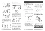
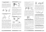
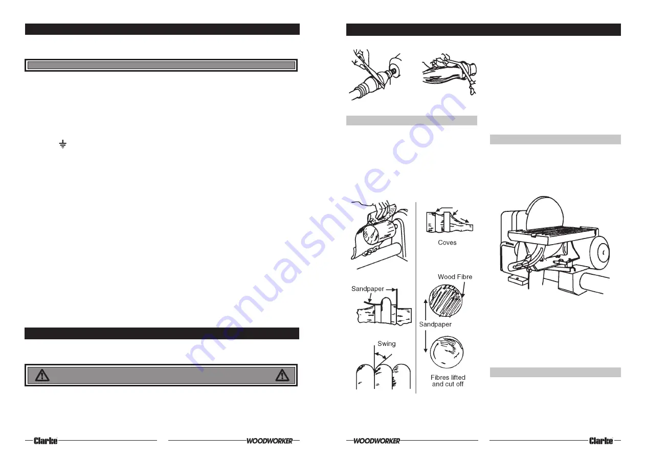
The application of the sandpaper strip is shown
in fig. 57. Care must be exercised in order to
prevent dubbing the corners of beads, shoulders
etc. It is good practice to finish sanding with
the work in reverse rotation. This is particularly
true when sanding basswood, white pine and
mahogany. These woods are hard to sand
clean since sanding packs the surface fuzz
down to the wood. Sanding very lightly, and
not too long with the lathe reversed, will lift the
fibres and cut them off cleanly.
2.
USE OF SANDING DISCS
A fully adjustable sanding table adds to the
scope and convenience of sanding operations.
Sanding is always done on the down travel side
of the wheel working on the other side would
kick the work upwards. Either second or third
speed can be used.
SANDING, BUFFING AND POLISHING
1. USING THE LATHE TO SAND TURNINGS
Turnings should be sanded with the lathe running
in second lowest speed. A large sheet of
sandpaper is useful for smoothing cylinders. All
other sanding operations are done with a
narrow strip of abrasive paper. The best finishing
grit is 3/0 for soft wood, 4/0 for hard woods. Worn
2/0 paper is often used, and is the equivalent of
3/0 or 4/0 new paper.
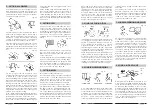
The sanding disc is a metal plate with a threaded
shank which fits the end of the lathe spindle.
Abrasive paper is glued to the machined
surface of the plate by means of a quick drying
cement supplied for this purpose. Abrasive discs
can be purchased or cut from the standard sizes
of abrasive paper.
3.
USE OF SANDING DRUMS
Standard sanding drums are usually rubber
cylinders which can be expanded to hold an
abrasive sleeve in place. Similar cylinders turned
on the lathe and covered with abrasive paper
27
Fig.58
Fig. 57
Fig. 56


