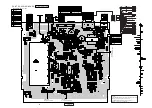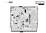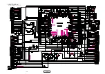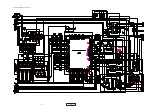
- 8 -
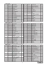
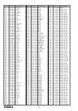
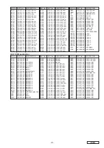
VRX630
28
347-6153-00
SHIELD SHEET
1
29
347-6113-00
SHIELD SHEET
1
30
331-2790-00
SHIELD CASE
1
31
855-5436-50
RCA CORD(VIDEO)
1
32
714-3005-80
MACHINE SCREW(M3x5)
3
33
092-0701-02
ANTENNA RECEPTACLE
1
34
714-2606-80
MACHINE SCREW(M2.6x6)
2
35
880-2084C
FM/AM TUNER PACK
1
36
353-0249-00
SHADE
1
37
855-5427-51
RCA CORD(AUDIO)
1
NO.
PART NO.
DESCRIPTION
Q'TY
NO.
PART NO.
DESCRIPTION
Q'TY
How to release LCD module
Refer to the exploded view of the main section on page 6.
1. R e m o v e t h e m a c h i n e s c r e w s ( N o . 2 7 x 2 ) a n d t h e
springs(No.26x2).
2. Remove the IT screws(No.18x4) and the tap screw(No.16x3)
in order to release the lower case(No.11).
3. Remove the escutchen(No.2) and the main PWB
assembly(No.9).
4. Pull out the LCD module,and release the flexible PWB of
the LCD module from the motor of the slide mechanism
assembly(No.5).(Fig.3)
5. Release the hooks of the Flexible PWB cover(No.1) from
the LCD module and the slide mechanism assembly(No.5).
6. Remove the flexible PWB cover(No.1) and the IT
screws(No.14x4).
Fig.3
Slide motor
Flexible PWB
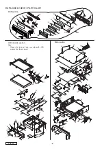
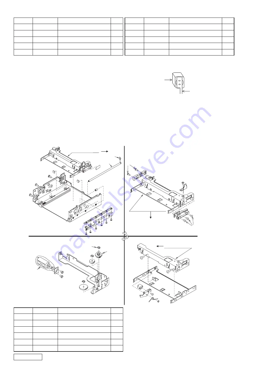
EXPLODED VIEW / PARTS LIST
Slide mechanism section : 948-0530-20
3
2
1
Slide plate assembly
Slide plate assembly
4
Slide plate sub-assembly
4
Slide plate sub-assembly
Gear plate assembly
Gear plate assembly
5
6
Note:Please replace the IT screws(No.4x5) for keeping
tight when you replace the motor ass'y or gear ass'y.
1
744-0041-00
E-RING
1
2
634-0016-00
GEAR ASSY
1
3
612-0402-00
SHAFT
1
4
780-2606-03
IT SCREW
5
5
634-0017-00
MOTOR ASSY
1
6
743-1500-01
E-RING
1
NO.
PART NO.
DESCRIPTION
Q'TY
Caution for the replacement of the motor assembly
After you replaced the motor assembly with new one,please
make sure that the current of the motor assembly is 50mA or
less when you input 8V as the power voltage.
If the current is over 50mA,loosen the screws, and adjust the
position of the motor assembly.
Then tighten the screws,and check the current again.
Содержание pro audio vrx 630
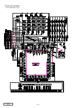
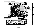
Страница 14: ...DCP PWB B4 section 14 VRX630 CIRCUIT DIAGRAM ...
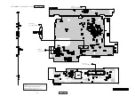
Страница 15: ...LCD PWB B3 section 15 VRX630 ...
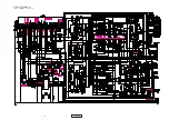
Страница 18: ...Main PWB B1 section 1 2 18 VRX630 CIRCUIT DIAGRAM ...
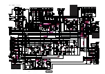
Страница 22: ...Digital PWB B2 section 1 2 22 VRX630 CIRCUIT DIAGRAM ...
Страница 23: ...Digital PWB B2 section 2 2 23 VRX630 ...

