


CLAGE
21
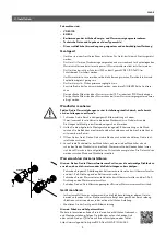
For further informations please use the online operation and installa
tion instruction. Please follow the link below or use the QR code via
smartphone or tablet.
https://www.clage.de/links/gma/DEXNextGMA912034382
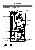
1
2
5
3
4
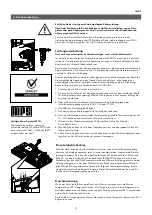
Structural prerequisites
• The appliance must be installed via a permanent connection. Heater must be
earthed!
• The electric wiring should not be injured.
• An allpole disconnecting device (e.g. via fuses) with a contact opening width of at
least 3 mm per pole should be provided at the installation end.
• To protect the appliance, a fuse element with trigger characteristic C must be fitted
with a tripping current commensurate with the nominal current of the appliance
Only by a specialist!
Please observe:
• VDE 0100
• The installation must comply with current IEC and national local regulations or any
particular regulations, specified by the local electricity supply company
• The rating plate and technical specifications
• The appliance must be earthed!
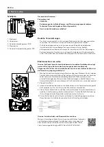
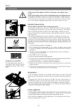
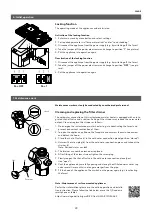
5. Electrical connection
Wiring diagram
1. Electronic circuitry
2. Heating element
3. Safety pressure cutout
4. Terminal strip
5. Safety thermal cutout
Note: If necessary, the connecting terminal can be displaced to the upper part of the
appliance. If you want to do so, please follow the instructions in the next chapter.
Check that the power supply is switched off prior to electrical connection!
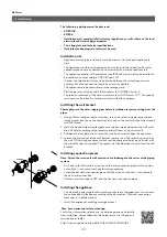
1. Dismantle approximately 6 cm off the connecting cable above the wall outlet. With
the smaller opening ahead, slide the water splash protection sleeve over the con
necting cable so that the sleeve is flush with the wall. This prevents any leaking
water from coming into contact with the electrical leads. It must not become dam
aged! The protection sleeve must be used!
2. Open the control panel.
3. Strip the individual wires and plug them in the connecting terminals according to
the wiring diagram. The appliance must be earthed.
4. Pull the protective sleeve over the connecting cables until the sleeve fits perfectly
in the recess of the intermediate panel and fix it with the sleeve fixing (A). Reinsert
the control panel and lock it on.
5. Place the hood on the appliance and screw in the fastening screw. After that you
can slide on the faceplate from the bottom up to the stop.
Electrical connection from below
A
Note: Load shedding and electrical connection from below


