background image

20

DEX Next

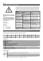
The following regulations must be observed:
•  VDE 0100
•  EN 806
•  Installation must comply with all statutory regulations, as well as those of the local 

electricity and water supply companies.

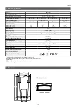
•  The rating plate and technical specifications
•  Only intact and appropriate tools must be used
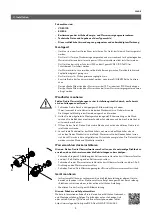
4. Installation

Installation site

•  Appliance must only be installed in frost­free rooms. Never expose appliance to 

frost.

•  The Appliance must be wall mounted and has to be installed vertically with water 

connectors downward or alternative transversely with water connections left.

•  The appliance complies with protection type IP25 and may therefore be installed in 

protection zone 1 according to VDE 0100 part 701.

•  In order to avoid thermal losses, the distance between the instantaneous water 

heater and the tap connection should be as small as possible.

•  The appliance must be accessible for maintenance work.
•  Plastic pipes may only be used if they conform to DIN 16893, Series 2. 
•  The specific resistance of the water must be at least 1100 Ωcm at 15 °C. The specific 

resistance can be asked for with your water distribution company.

Thoroughly rinse the water supply pipes before installation to remove soiling from the 

pipes.

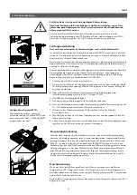
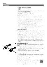
1.  Using a 12 mm hexagon socket screw key, screw the screw­in nipples according to 

image manual into the wall connections as shown in. The seals must be fully screwed 

into the thread.

2.  Hold the included mounting template according to image manual on the wall, mark 

the drill holes according to the template and drill them using a 6 mm drill. 

3.  Pull down the faceplate and unscrew the main hood screw to open the appliance.
4.  Loosen the knurled nut of the wall bracket, remove the wall bracket and screw it on 

the wall. Offset tiling or uneven surfaces can be compensated by up to 30 mm with 

the aid of the spacers supplied. The spacers are fitted between the wall and the wall 

bracket.

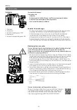
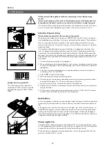
Installing the wall bracket

cold

warm

•  The electrical power supply cable may be connected in the upper part. In such case, 

the connection will be done according to the description “Electrical connection 

from above” in online manual.

•  Install the appliance according to image manual.

Installing the appliance

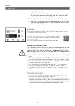
For further informations please use the online operation and installa­

tion instruction. Please follow the link below or use the QR code via 

smartphone or tablet.
https://www.clage.de/links/gma/DEX­Next­GMA­9120­34382

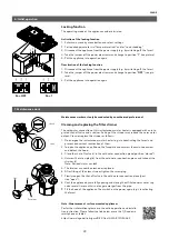
Note: Accessories and surface mounting

Note: Fasten the screw nuts with caution, to avoid damage to the valves or the piping 

system.

•  As shown in the illustration, screw the cold water connection piece with the union 

nut and the ½ inch seal onto the cold water connection. 

•  Screw the hot water connection piece with the union nut and the ½ inch seal onto 

the hot water connection.

Installing connection pieces

•  Put the water flow reducer “

D

” into the hot water connection piece.

D

Содержание DEX Next

Страница 1: ...Kurzanleitung Quick guide 11 19 de 2 en 13 E Komfortdurchlauferhitzer DEX Next E convenience instant water heater DEX Next ...

Страница 2: ...luss 10 Schaltplan 10 Bauliche Voraussetzungen 10 Elektroanschluss von unten 10 6 Erstinbetriebnahme 11 Leistungsumschaltung 11 Erneute Inbetriebnahme 11 Duschanwendung 11 7 Wartungsarbeiten 12 Sperrfunktion 12 Reinigung und Wechsel des Filtersiebes im Anschlussstück bei Unterputzanschluss 12 Geräteregistrierung Registrieren Sie Ihr Gerät online auf unserer Homepage und profitieren Sie von unseren...

Страница 3: ... ist ein elektronisch geregelter Durchlauferhitzer mit grafikfähigem E Paper Display und Sensortasten zur komfortab len und sparsamen Wasserversorgung einer oder mehrerer Zapfstelle n Die Elektronik regelt die Leistungsaufnahme in Abhängigkeit von der gewählten Auslauftemperatur der jeweiligen zulauftemperatur und auch der Durchflussmenge um die eingestellte Temperatur gradgenau zu erreichen und a...

Страница 4: ...rschiedenen Anwendungsbereiche in seinem Profil zu speichern Die Nutzerprofile können durch Tippen auf die linke Sensortaste aufgelistet und dann über die jeweilige Sensortaste unter den Profilbildern gewählt werden Profil individualisieren siehe Abschnitt Nutzer Anwendungen Hier können bereits voreingestellte Anwendungen ausgewählt werden Durch Tippen der Sensortaste unter der Anzeige öffnet sich...

Страница 5: ...ennen Sie den Durchlauferhitzer vom Netz indem Sie die Sicherungen aus schalten 2 Schrauben Sie den Strahlregler an der Entnahmearmatur ab und öffnen Sie zunächst das Kaltwasserzapfventil um die Wasserleitung sauber zu spülen und eine Verschmutzung des Gerätes oder des Strahlreglers zu vermeiden 3 Öffnen und schließen Sie danach mehrfach das zugehörige Warm wasser zapfventil bis keine Luft mehr au...

Страница 6: ...n durchgeführt werden Wenn sich ein Fehler an Ihrem Gerät mit dieser Tabelle nicht beheben lässt wen den Sie sich bitte an den Werkskunden dienst Halten Sie die Daten des Geräte typenschildes bereit 4 Selbsthilfe bei Problemen und Kundendienst CLAGE GmbH Werkskundendienst Pirolweg 1 5 21337 Lüneburg Deutschland Fon 49 4131 8901 40 Fax 49 4131 8901 41 E Mail service clage de 5 Produktdatenblatt nac...

Страница 7: ...hlussstück Feinfilter Spritzwasserschutztülle DEX Next Gerätehaube Rückflussverhinderer Durchflussgeber Temperaturfühler Temperaturfühler Auslaufrohr Geräteunterteil Wandhalter Warmwasser anschluss stück Durchfluss mengen regler 8l min 1 Übersichtsdarstellung Temperaturbegrenzer STB Heizelement Zulaufrohr Bedienfeld mit Klapphalter Montageanleitung Durchführungstülle G Zoll Einschraubnippel ...

Страница 8: ...bereich bei 15 C spezifischer Wasserwiderstand spezifische elektrische Leitfähigkeit 1100Ωcm 90mS m Zulauftemperatur 70 C Einschalt max Durchflussmenge 1 5l min 8 0 3 Druckverlust 0 2bar bei 2 5l min 1 3bar bei 9 0l min 4 Einstellbare Temperaturen 20 C 60 C Wasseranschluss G Zoll Gewicht mit Wasserfüllung 4 2kg Schutzklasse nach VDE I Schutzart Sicherheit IP25 Die Angabe entspricht der EU Verordnu...

Страница 9: ...g an den Warm wasser anschluss Wasseranschlussstücke installieren Spülen Sie die Wasserzuleitungen vor der Installation gründlich durch um Schmutz aus den Leitungen zu entfernen 1 Schrauben Sie die Einschraubnippel gemäß Bilderanleitung mit einem 12mm Innensechs kantschlüssel in die beiden Wandanschlüsse Dabei müssen die Dichtungen vollständig in das Gewinde eingeschraubt werden 2 Halten Sie die m...

Страница 10: ...che Netz dass die Strom versorgung ausgeschaltet ist 1 Manteln Sie das Anschluss kabel un gefähr 6cm über dem Wand austritt ab Schieben Sie die Spritz wasser schutztülle mit der kleineren Öffnung voran über das Anschluss kabel so dass die Schutz tülle wand bündig abschließt Diese verhin dert dass eventuell eindrin gendes Wasser mit den Elektro leitungen in Kontakt kommt Das Anschlusskabel darf nic...

Страница 11: ...kW 4 Mit OK die Ein stel lung bestätigen 5 Auf dem Typenschild die eingestellte Leistung kennzeichnen 6 Nach dem Einstellen der maximalen Geräteleistung wird die Wasser heizung nach ca 10 30 Sekunden kontinuierlichen Wasser flusses aktiviert 7 Öffnen Sie das Warmwasserzapfventil Überprüfen Sie die Funktion des Durchlauferhitzers 8 Machen Sie den Benutzer mit dem Gebrauch vertraut und übergeben Sie...

Страница 12: ...ise der Austausch des Siebes wie folgt vorzunehmen ist 1 Schalten Sie den Durchlauferhitzer an den Haussicherungen spannungsfrei und sichern Sie diese gegen unbeabsichtigtes Wiedereinschalten 2 Öffnen Sie das Gerät indem Sie die Blende nach unten abziehen die sich darunter befindliche Schraube lösen und die Haube abnehmen 3 Drehen Sie das Absperrventil im Kaltwasseranschlussstück a zu Position ges...

Страница 13: ...stalling connection pieces 20 Installing the appliance 20 5 Electrical connection 21 Wiring diagram 21 Structural prerequisites 21 Electrical connection from below 21 6 Initial operation 22 Selection of power rating 22 Reinstallation 22 Shower application 22 7 Maintenance work 23 Locking function 23 Cleaning and replacing the filter strainer 23 Registration Register your device online on our websi...

Страница 14: ...o 70 C so that operation in connection with reheat ing e g in solar systems is possible It is possible to use the instantaneous water heater in combination with an external load shedding relay for electronically controlled instantaneous water heaters refer to installing instructions Your product was manufactured from high quality reusable materials and components Please respect in case of discardi...

Страница 15: ... key to open the selection Tap on the sensor key under an application symbol to activate it The temperatures are set at the factory to the following values hand wash 35 C shower 38 C bath tub 42 C hot water 48 C To change the values select an application and set the new temperature Than press and hold the sensor key under your profile picture or under the application symbol for two seconds Status ...

Страница 16: ...l times Cleaning and maintenance This instantaneous water heater features an automatic air bubble protection to prevent it from inadvertently running dry Nevertheless the appliance must be vented before using it for the first time Each time the appliance is emptied e g after work on the plumbing system if there is a risk of frost or following repair work the appliance must be re vented before it i...

Страница 17: ...irs must only be carried out by authorised professionals If a fault in your appliance cannot be rectified with the aid of this table please contact the service organisation of your importer or the Central Customer Service Department Please have the details of the typeplate at hand 4 Trouble shooting and service CLAGE GmbH After Sales Service Pirolweg 1 5 21337 Lüneburg Germany Phone 49 4131 8901 4...

Страница 18: ...al Frame Cold water connection Fine filter Water splash protection sleeve DEX Next hood Non return valve Flow sensor Thermal sensor set Thermal sensor set Outlet pipe Bottom part Wall bracket Hot water connection Flow limiter 8l min 1 Overview Safety thermal cut out Heating element Inlet pipe Control panel with bracket Installation instruction Grommet Screw in nipples inch ...

Страница 19: ...ystem IES 15 C Required specific water resistance Specific electrical conductivity 1100Ωcm 90mS m Inlet temperature 70 C Flow rate to switch on max flow rate 1 5l min 8 0 3 Pressure loss 0 2bar at 2 5l min 1 3bar at 9 0l min Temperature range 20 60 C Water connection G inch Weight when filled with water 4 2kg VDE class of protection I Type of protection safety IP25 The declaration complies with th...

Страница 20: ...own in The seals must be fully screwed into the thread 2 Hold the included mounting template according to image manual on the wall mark the drill holes according to the template and drill them using a 6mm drill 3 Pull down the faceplate and unscrew the main hood screw to open the appliance 4 Loosen the knurled nut of the wall bracket remove the wall bracket and screw it on the wall Offset tiling o...

Страница 21: ...pressure cut out 4 Terminal strip 5 Safety thermal cut out Note If necessary the connecting terminal can be displaced to the upper part of the appliance If you want to do so please follow the instructions in the next chapter Check that the power supply is switched off prior to electrical connection 1 Dismantle approximately 6cm off the connecting cable above the wall outlet With the smaller openin...

Страница 22: ...maximum allowable power rating depending on the local situation via sensor keys 18 21 24 or 27kW 4 Select OK to confirm the setting 5 Mark the set power rating on the rating plate 6 After having set the maximum allowable power rating the heating element will be activated after approx 10 30sec of continuous water flow 7 Open the hot water tap Check the function of the appliance 8 Explain the user h...

Страница 23: ...revent inadvertent reactivation of them 2 To open the appliance pull down the faceplate and unscrew the main hood screw and detach the hood 3 Close the shut off valve a in the cold water connection piece position closed 4 Unscrew the screw plug b from the cold water connection piece and take out the strainer c Note Residual water can leak 5 The strainer can now be cleaned or re placed 6 After fitt...

Страница 24: ...utschland Telefon 49 4131 8901 0 Telefax 49 4131 83200 E Mail service clage de Internet www clage de Technische Änderungen Änderungen der Ausführung und Irrtum vorbehalten Subject to technical changes design changes and errors 9120 34382 11 19 ...

Отзывы: