


21
8.
Adding the product to your Home Wireless ZigBee
Network
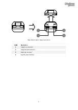
STEP 1
Open the front cover, you will see an
USB socket.
STEP 2
Plug the CG101UTU cable into the
USB socket of the product, and then
plug the other end of the CG101UTU
cable into the mini USB end of the
CG101UTC cable.
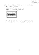
STEP 3
Plug the CG101UTC cable into the
USB port of a PC which has been
installed with CityGrow’s HomeNET
Planner 2 Software.
STEP 4
Refer to the user manual of
“HomeNET Planner 2” Software to
program and set the address of the
product.
2
2
3
Содержание CG400 Series
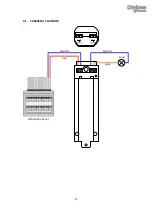
Страница 16: ...13 4 1 CG400SW CG400DM Distribution Panel Live Neutral Neutral Load Load L N OUTPUT N L INPUT...
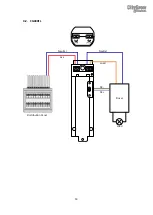
Страница 17: ...14 4 2 CG400FL Distribution Panel Live Neutral Neutral Load Load L N OUTPUT N L INPUT Driver DC DC...
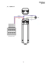
Страница 18: ...15 4 3 CG400S2 CCP Distribution Panel Live Neutral Neutral L1 Load L1 L2 OUTPUT N L INPUT L2...


