


3-2
Cisco UCS C220 Server Installation and Service Guide
OL-25760-01
Chapter 3 Maintaining the Server
Status LEDs and Buttons
Status LEDs and Buttons
This section describes the location and meaning of LEDs and buttons and includes the following topics
•
Front Panel LEDs, page 3-2
•
Rear Panel LEDs and Buttons, page 3-4
•
Internal Diagnostic LEDs, page 3-6
Front Panel LEDs
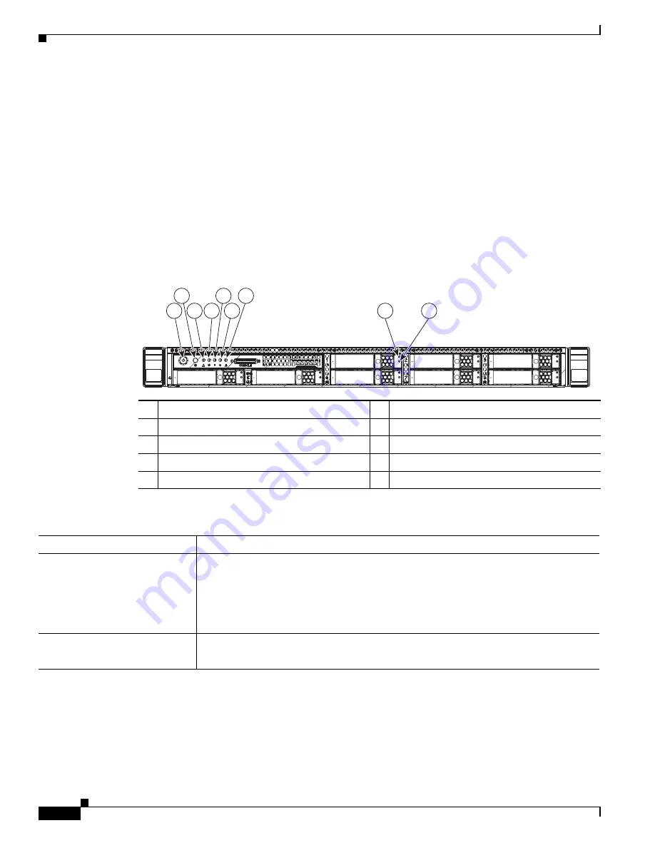
Figure 3-1
shows the front panel LEDs.
Table 3-1
defines the LED states.
Figure 3-1
Front Panel LEDs
HDD4
HDD5
HDD1
HDD6
HDD2
HDD7
HDD3
HDD8
8
9
1
3
4
6
7
5
2
331691
1
Power button/Power status LED
6
Power supply status LED
2
Identification button/LED
7
Network link activity LED
3
System status LED
8
Hard drive fault LED
4
Fan status LED
9
Hard drive activity LED
5
Temperature status LED
–
Table 3-1
Front Panel LEDs, Definitions of States
LED Name
State
Power button/Power status LED
•
Off—There is no AC power to the server.
•
Amber—The server is in standby power mode.
Power is supplied only to the CIMC
and some motherboard functions.
•
Green—The server is in main power mode. Power is supplied to all server
components.
Identification
•
Off—The Identification LED is not in use.
•
Blue—
The Identification LED is activated
.
Содержание UCS C220 M3
Страница 12: ...xii Cisco UCS C220 Server Installation and Service Guide OL 25760 01 Preface ...
Страница 14: ...xiv Cisco UCS C220 Server Installation and Service Guide OL 25760 01 Preface ...
Страница 20: ...1 6 Cisco UCS C220 Server Installation and Service Guide OL 25760 01 Chapter 1 Overview ...
Страница 134: ...D 2 Cisco UCS C220 Server Installation and Service Guide OL 25760 01 Appendix D Installation for Cisco UCS Integration ...


