a) Align the two screw holes on a rear rack-mount bracket to the middle two screw holes in the remaining six screw
holes on a side of the chassis. If you are aligning the guide to holes that are near the port connections end of the
chassis, see Callout 3 in the previous figure. Otherwise, see Callout 7 in the previous figure.
b) Attach the guide to the chassis using two M4 screws (see Callout 4 or 8 in the previous figure). Tighten the screws
to 12 in-lb (1.36 N·m) of torque.
c) Repeat Step 2 for the other rear rack-mount bracket on the other side of the switch.
Step 3
If you are not installing the chassis into a grounded rack, you must attach a customer-supplied grounding wire to the
chassis as explained in
Grounding the Chassis, on page 20
. If you are installing the chassis into a grounded rack, you
can skip this step.
Step 4
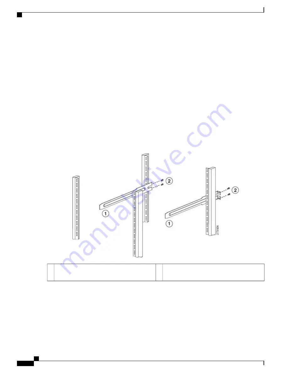
Install the slider rails on the rack or cabinet as follows:
a) Determine which two posts of the rack or cabinet you should use for the slider rails. Of the four vertical posts in the
rack or cabinet, two will be used for the front mount brackets attached to the easiest accessed end of the chassis, and
the other two posts will have the slider rails.
b) Position a slider rail at the desired level on the back side of the rack and use two 12-24 screws or two 10-32 screws,
depending on the rack thread type, to attach the rails to the rack (see the following figure). Tighten 12-24 screws to
30 in-lb (3.39 N·m) of torque and tighten 10-32 screws to 20 in-lb (2.26 N·m) of torque.
Two customer-supplied 12-24 or 10-32 screws used
to attach each slider rail to the rack
2
Slider rail with screw holes aligned to screw holes in
rack
1
c) Repeat Step 3 to attach the other slider rail to the other side of the rack.
To make sure that the slider rails are at the same level, you should use a level tool, tape measure, or carefully count
the screw holes in the vertical mounting rails.
Step 5
Insert the switch into the rack and attach it as follows:
a) Holding the switch with both hands, position the two rear rack-mount brackets on the switch between the rack or
cabinet posts that do not have slider rails attached to them (see the following figure).
Cisco Nexus 93108TC-FX ACI Mode Hardware Installation Guide
18
Installing the Switch Chassis
Installing the Switch
Содержание Nexus 93108TC-FX
Страница 6: ...Cisco Nexus 93108TC FX ACI Mode Hardware Installation Guide vi Contents ...
Страница 14: ...Cisco Nexus 93108TC FX ACI Mode Hardware Installation Guide 4 Overview Overview ...
Страница 22: ...Cisco Nexus 93108TC FX ACI Mode Hardware Installation Guide 12 Preparing the Site Clearance Requirements ...
Страница 65: ...Cisco Nexus 93108TC FX ACI Mode Hardware Installation Guide 55 LEDs Power Supply LEDs ...
Страница 66: ...Cisco Nexus 93108TC FX ACI Mode Hardware Installation Guide 56 LEDs Power Supply LEDs ...


