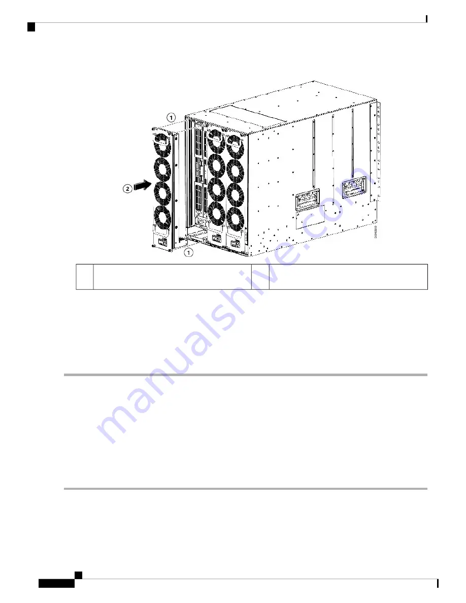
Figure 30: Installing a Fan Tray
Press the whole fan tray into the chassis slot.
2
Align the four pins in the fan tray with four holes
in the chassis.
1
b) With the electrical contacts on the fan tray aligned to contacts on the back plane, press the fan tray fully into the slot.
The front of the fan tray should be even with the fronts of the other fan trays and the four captive screws on the fan
tray should be aligned to four screw holes in the chassis.
c) Screw in each of the four captive screws on the front of the fan tray to secure the fan tray to the chassis. Tighten each
screw to 8 in-lb (0.9 N·m) of torque.
d) Verify that the Status LED is green. For more information about the LED states, see
Replacing Fabric 2 Modules with Fabric 3 Modules
If you are running Cisco NX-OS 8.3(1) or a later release on a Cisco Nexus 7710 switch, you can replace all
the Fabric 2 modules with Fabric 3 modules. You can replace the modules during operations if you replace
each module within a couple of minutes so that the switch can maintain its designed airflow. The replacement
procedure is non-disruptive to switch operations if there is at least one fabric module installed and operating
in the switch while you replace the other fabric module.
To replace Fabric 2 modules with Fabric 3 modules, follow these steps:
Step 1
Verify that the switch is running Cisco NX-OS Release 8.3(1) or a later release.
Step 2
Replace the Fabric 2 module that is in the lowest numbered fabric slot.
Step 3
Enter the
show module xbar
command, as shown in the example below, to display the types of fabric modules installed
in the fabric slots.
Cisco Nexus 7710 Switch Site Preparation and Hardware Installation Guide
OL-30452-01.
128
Installing or Replacing Modules, Fan Trays, and Power Supplies
Replacing Fabric 2 Modules with Fabric 3 Modules


