


7-11
Network Processing Engine and Network Services Engine Installation and Configuration
OL-4448-12
Chapter 7 NPE-G1 and NPE-G2 Installation and Configuration Information
Removing the Network Processing Engine
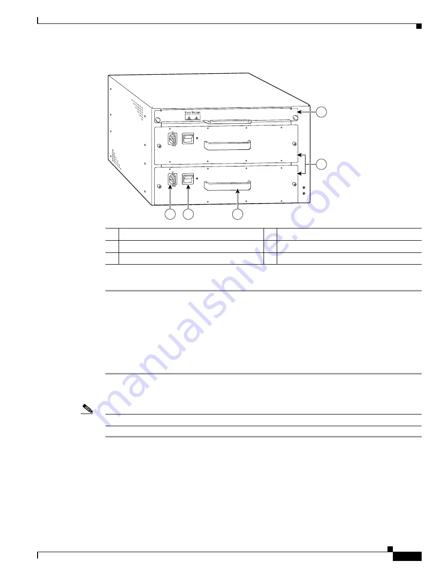
Figure 7-2
Disconnecting Power from a Cisco uBR7246VXR AC-Input Power Supply
Step 4
Repeat Step 1 through Step 3 if a second power supply is installed.
This completes the procedure for disconnecting AC-input power from a Cisco uBR7246VXR router. Go
to the
“Removing the NPE or NSE-1” section on page 7-16
.
Disconnecting AC-Input Power from a Cisco uBR7225VXR Router
To disconnect AC-input power from a Cisco uBR7225VXR router, complete the following steps:
Step 1
Unplug the input power cable from the power source.
Step 2
Unplug the other end of the input power cable from the power supply.
Note
The Cisco uBR7225VXR router power supply does not have a cable retention-clip.
Disconnecting DC-Input Power from a Cisco 7200 VXR Router
To disconnect DC-input power from a Cisco 7200 VXR router, complete the following steps.
1
AC-input receptacle
4
Network processing engine
2
Power switch
5
AC-input power supply
3
Handle
66434
3
4
2
1
5


