16
Catalyst 6500 Series DFC, DFC3A, DFC3B, and DFC3BXL Installation Note
78-11627-04
Installing the DFC
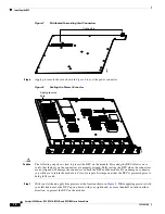
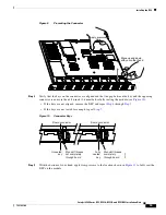
Figure 11
Seating the Distributed Forwarding Card on the Module
Note
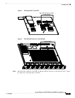
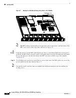
The DFC is fully seated when there is no gap between the connector keys, and the bottom of the
DFC is in contact with the tops of the standoffs (see
Figure 10
).
Caution
Using the screws to seat the DFC could warp the card.
Before
you install and tighten the securing screws,
ensure that the DFC is fully seated by visually verifying that there is no gap between the male and female
keys on the connectors and that the bottom of the DFC is in contact with the tops of the standoffs
(see
Figure 10
).
Step 10
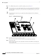
Use a Phillips-head screwdriver to install the two screws at the front of the DFC and the one screw at the
power connector in the order shown in
Figure 12
.
Note
You should visually verify that there are standoffs beneath the mounting holes before installing the
securing screws.
WS-X5530
48444
STA
TUS
LIN
E
LIN
E
1
1
2
LIN
E
LIN
E
3
4
LIN
E
LIN
E
5
6
LIN
E
LIN
E
7
8
LIN
E
LIN
E
9
10
LIN
E
LIN
E
11
12
LIN
E
LIN
E
13
14
LIN
E
LIN
E
15
16
2
3
4
5
6
7
8
9
10
11
12
13
14
15
16
Apply pressure
here

