15
Catalyst 6500 Series DFC, DFC3A, DFC3B, and DFC3BXL Installation Note
78-11627-04
Installing the DFC
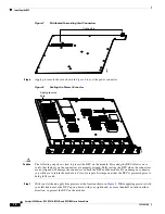
Figure 9
Preseating the Connector
Step 8
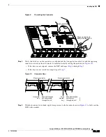
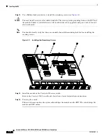
Verify that the keys on the connector are aligned and that the gap between the key and the opposing
connector is no more than 1/16 inch (1.6 mm) before fully seating the module (see
Figure 10
):
•
If the keys are not aligned, remove the DFC and repeat
Step 4
through
Step 7
.
•
If the keys are not seated far enough, repeat
Step 7
.
Figure 10
Connector Keys
Step 9
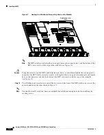
With the bottom of your hand, apply firm pressure to the location shown in
Figure 11
to fully seat the
DFC on the module.
WS-X5530
52721
STA
TUS
LINE
LINE
1
1
2
LINE
LINE
3
4
LINE
LINE
5
6
LINE
LINE
7
8
LINE
LINE
9
10
LINE
LINE
11
12
LINE
LINE
13
14
LINE
LINE
15
16
2
3
4
5
6
7
8
9
10
11
12
13
14
15
16
Apply pressure
here
Move up and down
with your other hand
Board connector
Standoff threads
not completely
through board
Standoff threads
completely
through board
Board connector
Unseated
key
Fully
seated
key
52722

