


Equipment
The following equipment is necessary to install the chassis and verify that it is ready for configuration:
•
Standard 19-inch (48.26 cm) equipment rack (4-post or 2-post) or telecommunications cabinet with
mounting hardware.
The rack/cabinet must be installed in accordance with OEM recommendations
and local practices for electrical/grounding and seismic conditions.
•
Multiple -48 VDC power feeds terminated at the rack/cabinet.
•
Voltmeter to measure input voltages at the PFU terminals.
•
Heat gun for installing shrink wrap tubing over power cable lugs.
•
Computer with a DB9 RS-232C serial port or a terminal server port that will connect to the RJ45 Console
port on the chassis management MIO/UMIO cards for accessing the Command Line Interface (CLI).
•
Pallet jack and/or chassis lift to move and position the ASR 5500 chassis. Without such mechanical
assistance, moving and positioning the chassis will require multiple craftpersons trained to safely handle
heavy rack-mounted units.
Site Prerequisites
This section summarizes power, grounding, environment, and clearance requirements that must be met prior
to installing and operating the ASR 5500. For detailed information, refer to the
Technical Specifications
chapter.
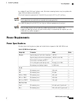
Power and Grounding
Each PFU requires eight power feeds of 80A @ -48VDC (nominal). The feeds should be routed to the
installation rack from the site power supply using adequately sized conductors and circuit breakers in accordance
with local electrical codes. For additional information on power requirements, see the
Technical Specifications
chapter.
The chassis must be grounded to a site ground point using the recommended conductors and lugs. The ground
point should be in close proximity to the ASR 5500 chassis to assure adequate conductivity.
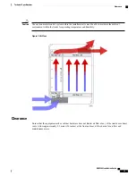
Environment
The site's heating ventilation and air conditioning (HVAC) systems must be sized to maintain the operating
temperatures and relative humidity specified in the
Technical Specifications
chapter. HVAC capacity
requirements will vary based on the system configuration and associated power draw, as well as the operational
characteristics of other equipment installed at the site.
ASR 5500 Installation Guide
27
Installation Procedure Overview
Equipment
Содержание ASR 5500
Страница 12: ...ASR 5500 Installation Guide xii Contents ...
Страница 16: ...ASR 5500 Installation Guide xvi About this Guide Contacting Customer Support ...
Страница 40: ...ASR 5500 Installation Guide 24 Technical Specifications Chassis Grounding ...
Страница 74: ...ASR 5500 Installation Guide 58 Card Installation Save Shipping Cartons ...
Страница 88: ...ASR 5500 Installation Guide 72 MIO Port Cabling Cleaning Fiber Optic Connectors ...
Страница 112: ...ASR 5500 Installation Guide 96 System Power up show leds Command ...
Страница 130: ...ASR 5500 Installation Guide 114 Initial System Configuration Additional Configuration Tasks ...
Страница 164: ...ASR 5500 Installation Guide 148 Replaceable Components Returning Failed Components ...
Страница 186: ...ASR 5500 Installation Guide 170 Console Port to Cisco Server Cabling Configuration ...
Страница 192: ...ASR 5500 Installation Guide 176 RMA Shipping Procedures Rear Cards ...