background image

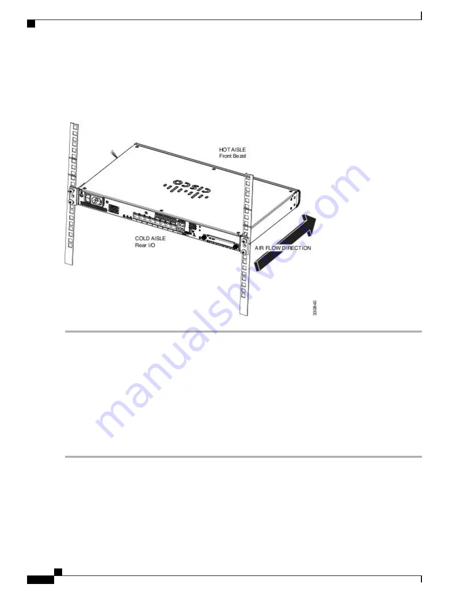
We recommend that you install the chassis with the rear panel facing the cold aisle. (See the following illustration for
an example of air flow from back to front.)

Figure 18: Chassis Installed in the Rack

What to Do Next

You can now install the cables and power cord, as described in

Connect Cables, Turn on Power, and Verify

Connectivity, on page 22

.

Connect Cables, Turn on Power, and Verify Connectivity

After positioning or mounting the ASA, follow these steps to connect cables, turn on power, and verify
connectivity:

Step 1

Connect the network cables:

a) Management interface

Using this Management 1/1 Gigabit Ethernet port, you can connect a management computer

directly with an Ethernet cable, or you can connect the computer and the ASA to the same management network. Be
sure the PC is configured to obtain an IP address using DHCP.

   Cisco ASA 5508-X and ASA 5516-X Hardware Installation Guide

22

Online Only   

Mount and Connect

Connect Cables, Turn on Power, and Verify Connectivity

Содержание ASA 5508-X

Страница 1: ...tion Guide First Published 2015 04 07 Last Modified 2017 06 16 Americas Headquarters Cisco Systems Inc 170 West Tasman Drive San Jose CA 95134 1706 USA http www cisco com Tel 408 526 4000 800 553 NETS 6387 Fax 408 527 0883 Text Part Number Online Only ...

Страница 2: ...MPLIED INCLUDING WITHOUT LIMITATION THOSE OF MERCHANTABILITY FITNESS FOR A PARTICULAR PURPOSE AND NONINFRINGEMENT OR ARISING FROM A COURSE OF DEALING USAGE OR TRADE PRACTICE IN NO EVENT SHALL CISCO OR ITS SUPPLIERS BE LIABLE FOR ANY INDIRECT SPECIAL CONSEQUENTIAL OR INCIDENTAL DAMAGES INCLUDING WITHOUT LIMITATION LOST PROFITS OR LOSS OR DAMAGE TO DATA ARISING OUT OF THE USE OR INABILITY TO USE THI...

Страница 3: ...R 2 Installation Preparation 17 Installation Warnings 17 Safety Recommendations 18 Maintain Safety with Electricity 18 Prevent Electrostatic Discharge Damage 19 Site Environment 19 Site Considerations 20 Power Supply Considerations 20 Equipment Rack Configuration Considerations 20 C H A P T E R 3 Mount and Connect 21 Rack mount the ASA 21 Connect Cables Turn on Power and Verify Connectivity 22 Con...

Страница 4: ...Windows 24 Connect to the Console Port with Mac OS X 26 Connect to the Console Port with Linux 26 C H A P T E R 4 Maintenance and Upgrades 27 Replace the SSD 27 Cisco ASA 5508 X and ASA 5516 X Hardware Installation Guide iv Online Only Contents ...

Страница 5: ...16 X The Cisco ASA 5508 X and the ASA 5516 X adaptive security appliances are part of the ASA 5500 X of next generation mid range ASAs and are built on the same security platform as the rest of the ASA family Your ASA 5508 X and ASA 5516 X ship with either ASA or Firepower Threat Defense software preinstalled To reimage your device see Reimage the Cisco ASA or Firepower Threat Defense Device Note ...

Страница 6: ...and Safety Information for the Cisco ASA 5500 X Series appliances and follow proper safety procedures Note Package Contents The following figure shows the package contents for the ASA 5508 X and ASA 5516 X Note that the contents are subject to change and your exact contents might contain additional or fewer items Figure 1 Package Contents USB console cable Type A to Type B 2 Chassis 1 Four 10 32 P...

Страница 7: ...more information about the ASA power supply 2 Power switch Standard rocker type power on off switch 1 Network data ports Eight Gigabit Ethernet RJ 45 8P8C network I O interfaces The ports are numbered from left to right 1 2 3 4 5 6 7 8 Each port includes a pair of LEDs one each for connection status and link status The ports are named and numbered Gigabit Ethernet 1 1 through Gigabit Ethernet 1 8 ...

Страница 8: ...port A standard USB Type A port is provided allowing attachment of an external device such as mass storage See Internal and External Flash Storage on page 6 for additional information 7 SSD bay Covered slot in which the SSD is installed You can replace this drive if it fails See Replace the SSD on page 27 for more information 10 SSD LED Status light for installed solid state drive SSD See LEDs on ...

Страница 9: ...r after June 2017 Unlit No SSD present or no activity on the SSD Green Activity on the SSD See Replace the SSD on page 27 for information on replacing a failed SSD Note SSD Network Port Status On the rear panel a pair of LEDs Link status and connection Status for each of the eight Gigabit Ethernet network ports and the Gigabit Ethernet Management port Link status L Unlit No link or port is not in ...

Страница 10: ...t support a remote dial in modem You can use a standard management cable Cisco part number 72 3383 01 to convert the RJ45 to DB9 connection if necessary Mini USB Type B Port The Mini USB Type B port lets you connect to a USB port on an external computer For Linux and Macintosh systems no special driver is required For Windows systems you must download and install a USB driver available on software...

Страница 11: ...and mount the partition to disk1 again however data might be lost Solid State Drive The ASA 5508 X and 5516 X ship with an SSD installed that provides storage support The SSD in the ASA 5508 X has 80 GB of useable space and is field replaceable The SSD in the ASA 5516 X has 1000 GB of usable space and is also field replaceable See Replace the SSD on page 27 for information about replacing it Power...

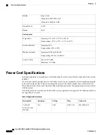
Страница 12: ...nce If you do not order the optional power cord with the system you are responsible for selecting the appropriate power cord for the product Using a non compatible power cord with this product may result in electrical safety hazard Orders delivered to Argentina Brazil and Japan must have the appropriate power cord ordered with the system Only the approved power cords provided with the security app...

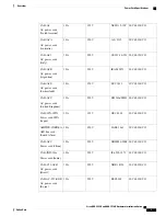
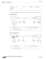
Страница 13: ...250V 10A CAB ACU AC power cord United Kingdom IEC 60320 C13 JIS C8303 125V 12A CAB JPN 3PIN Power cord 3PIN Japan IEC 60320 C13 SABS 1661 250V 10A AIR PWR CORD SA AIR line cord South Africa IEC 60320 C13 GB2009 1 2008 250V 10A CAB ACC Power cord China IEC 60320 C13 IS 6538 1971 250V 10A CAB IND 10A Power cord India IEC 60320 C13 NBR 14136 250V 10A CAB C13 ACB AC power cord Brazil IEC 60320 C13 KSC...

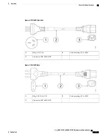
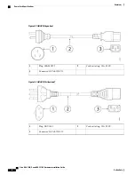
Страница 14: ...untry listed in the table above Figure 4 CAB ACE Europe Cord set rating 10A 250V 2 Plug CEE 7 VII 1 Connector IEC 60320 C13 3 Figure 5 CAB AC North America Cord set rating 10A 125V 2 Plug NEMA 5 15P 1 Connector IEC 60320 C13 3 Cisco ASA 5508 X and ASA 5516 X Hardware Installation Guide 10 Online Only Overview Power Cord Specifications ...

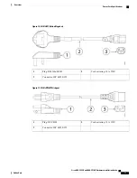
Страница 15: ...V 2 Plug A S 3112 1 Connector IEC 60320 C13 3 Figure 7 CAB ACI Italy Cord set rating 10A 250V 2 Plug CE123 16 VII 1 Connector IEC 60320 C13 3 Cisco ASA 5508 X and ASA 5516 X Hardware Installation Guide Online Only 11 Overview Power Cord Specifications ...

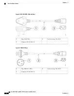
Страница 16: ... 2 Plug IRAM 2073 1 Connector IEC 60320 C13 3 Figure 9 CAB ACS Switzerland Cord set rating 10A 250V 2 Plug SEV 1011 1 Connector IEC 60320 C13 3 Cisco ASA 5508 X and ASA 5516 X Hardware Installation Guide 12 Online Only Overview Power Cord Specifications ...

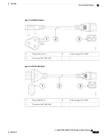
Страница 17: ... 2 Plug BS1363a SS145 1 Connector IEC 60320 C13 3 Figure 11 CAB JPN 3PIN Japan Cord set rating 12A 125V 2 Plug JIS C8303 1 Connector IEC 60320 C13 3 Cisco ASA 5508 X and ASA 5516 X Hardware Installation Guide Online Only 13 Overview Power Cord Specifications ...

Страница 18: ...A 250V 2 Plug SABS 1661 1 Connector IEC 60320 C13 3 Figure 13 CAB ACC China Cord set rating 10A 250V 2 Plug GB2009 1 2008 1 Connector IEC 60320 C13 3 Cisco ASA 5508 X and ASA 5516 X Hardware Installation Guide 14 Online Only Overview Power Cord Specifications ...

Страница 19: ... Plug IS 6538 1971 1 Connector IEC 60320 C13 3 Figure 15 CAB C13 ACB Brazil Cord set rating 10A 250V 2 Plug NBR 14136 1 Connector IEC 60320 C13 3 Cisco ASA 5508 X and ASA 5516 X Hardware Installation Guide Online Only 15 Overview Power Cord Specifications ...

Страница 20: ...250V 2 Plug KSC8305 1 Connector IEC 60320 C13 3 Figure 17 CAB ACTW Taiwan Cord set rating 10A 250V 2 Plug CNS10917 1 Connector IEC 60320 C13 3 Cisco ASA 5508 X and ASA 5516 X Hardware Installation Guide 16 Online Only Overview Power Cord Specifications ...

Страница 21: ...ect the power at the circuit breaker on DC units Warning Before working on equipment that is connected to power lines remove jewelry including rings necklaces and watches Metal objects will heat up when connected to power and ground and can cause serious burns or weld the metal object to the terminals Warning During this procedure wear grounding wrist straps to avoid ESD damage to the card Do not ...

Страница 22: ...he following sections to help ensure your safety and to protect the chassis This information may not address all potentially hazardous situations in your working environment so be alert and exercise good judgment at all times Observe these safety guidelines Keep the area clear and dust free before during and after installation Keep tools away from walkways where you and others might trip over them...

Страница 23: ... and it can damage equipment and impair electrical circuitry resulting in intermittent or complete failure Always follow ESD prevention procedures when removing and replacing components Ensure that the chassis is electrically connected to an earth ground Wear an ESD preventive wrist strap ensuring that it makes good skin contact Connect the grounding clip to an unpainted surface of the chassis fra...

Страница 24: ...tages and power levels in the appliance input voltage Install proper grounding for the site to avoid damage from lightning and power surges The chassis does not have a user selectable operating range Refer to the label on the chassis for the correct appliance input power requirement Install an uninterruptible power source for your site if possible Equipment Rack Configuration Considerations Consid...

Страница 25: ...minal or PC page 24 Rack mount the ASA The ASA ships with rack mount brackets or ears which you can install on the front or the rear of the chassis Follow these steps to install your ASA in a rack Step 1 Attach both brackets to the sides of the ASA chassis either to the front or rear After the brackets are secured to the chassis you can mount it in the rack Step 2 Attach the chassis to the rack Ci...

Страница 26: ...Connectivity After positioning or mounting the ASA follow these steps to connect cables turn on power and verify connectivity Step 1 Connect the network cables a Management interface Using this Management 1 1 Gigabit Ethernet port you can connect a management computer directly with an Ethernet cable or you can connect the computer and the ASA to the same management network Be sure the PC is config...

Страница 27: ...le is plugged into the USB console port the RJ 45 port becomes inactive Conversely when the USB cable is removed from the Mini USB Type B port the RJ 45 port becomes active See Connect to a Console Terminal or PC on page 24 for specific instructions for connecting the console port c Gigabit Ethernet ports For the network interfaces use standard RJ 45 Ethernet cables You can use any available Gigab...

Страница 28: ...Connect to a Console Terminal or PC The serial ports provide administrative access to the ASA either with a console terminal or a PC To configure the ASA through the CLI you must establish a connection between the ASA console port and either a terminal or a PC This section describes how to connect to a console terminal or a PC and contains the following topics Connect to the Console Port with Micr...

Страница 29: ... Connect the end of the cable with the DB 9 connector or USB Type A to the terminal or PC If your terminal or PC has a console port that does not accommodate a DB 9 connector you must provide an appropriate adapter for that port The LED for the console port turns green and within a few moments the Found New Hardware Wizard appears Step 5 Follow the instructions to complete the driver installation ...

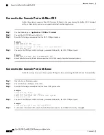
Страница 30: ...er Ctrl z followed by Ctrl to disconnect the OS X USB console from the Terminal window Connect to the Console Port with Linux Follow these steps to connect a Linux system USB port to the console using the built in Linux Terminal utility Step 1 Open the Linux Terminal window Step 2 Connect the Linux USB port to the ASA Step 3 Enter the following commands to find the Linux USB port number Example ro...

Страница 31: ...to power off the ASA to do so Follow these steps to replace a failed SSD in an ASA Step 1 Loosen the thumb screws on both sides of the SSD bay and pull the existing SSD out of the bay Step 2 Insert the new SSD into the bay and push it in until it is seated Step 3 Tighten the thumb screws on both sides of the SSD bay Step 4 Check the SSD LED to make sure the SSD is seated properly and functioning S...

Страница 32: ...Cisco ASA 5508 X and ASA 5516 X Hardware Installation Guide 28 Online Only Maintenance and Upgrades Replace the SSD ...

Отзывы: