1-7
Cisco Aironet 1530 Series Outdoor Access Point Hardware Installation Guide
OL-30864-01
Chapter 1 Overview
Hardware Features
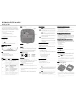
Antenna Port Locations
shows the antenna port locations for model AIR-CAP1532E
-x-
K9. The ports used depend on
the optional antennas ordered.
Figure 1-6
External Antenna Port Locations for Access Point Models AIR-CAP1532E-x-K9
Radio Operation
Warning
In order to comply with radio frequency (RF) exposure limits, the antennas should be placed no less
than 20 cm (8”) from your body or nearby persons.
Statement 339
Warning
Do not locate the antenna near overhead power lines or other electric light or power circuits, or
where it can come into contact with such circuits. When installing the antenna, take extreme care
not to come into contact with such circuits, because they may cause serious injury or death. For
proper installation and grounding of the antenna, please refer to national and local codes (for
example, U.S.: NFPA 70, National Electric Code, Article 180, Canada: Canadian Electrical Code,
Section 54).
Statement 1052
Warning
Only trained and qualified personnel should be allowed to install, replace, or service this equipment.
Statement 1030
1
Antenna port 1 – Type N connector
2
Antenna port 2- Type N connector
3
Antenna port 3– Type N connector (with cap)
4
Antenna port 4- Type N connector (with cap)
351321
4
2
3
1