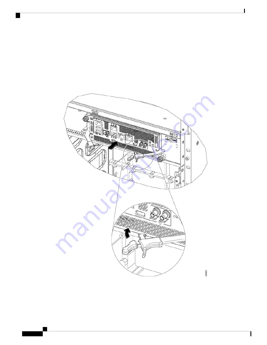
d) Rotate the levers firmly all the way to the front of the chassis. Then firmly push the tip of the levers
towards the faceplate till the latch hook locks in place behind the faceplate. You may hear a click or see
the latch engage. (See Callout 1 in the below figure.)
Make sure that the other end of both levers engages behind the latching slot on the faceplate so that the
card fully seats onto the connectors on the midplane.
To confirm that the card is installed properly, pull the black tip of each ejector lever lightly, and
make sure the lever does not pop out.
Note
Figure 82: Install Route Processor Card into Chassis
e) Screw in the two captive screws to secure the card to the chassis. Tighten the screws to 8 in-lb (0.9 N·m)
of torque.
f)
Attach the cables to the card.
Hardware Installation Guide for Cisco 8800 Series Routers
114
Replace Chassis Components
Replace a Route Processor Card
Содержание 8800 Series
Страница 6: ...Hardware Installation Guide for Cisco 8800 Series Routers vi Contents ...
Страница 30: ...Hardware Installation Guide for Cisco 8800 Series Routers 24 Unpack and Install the Chassis Unpack the Chassis ...
Страница 112: ...Hardware Installation Guide for Cisco 8800 Series Routers 106 LEDs Line Card LEDs ...


