DS726PP2
49
CS4525
6.1.8.5
PWM_SIG Logic-Level Output Configurations
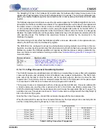
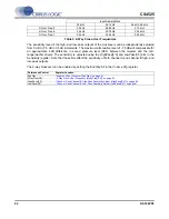
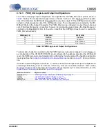
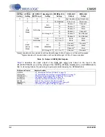
Four channel mapping output configurations are supported for the PWM_SIG output pins as shown in
below. The configurations support stereo, channel 1 with sub, and channel 2 with sub applica-
tions. When disabled, the PWM_SIG pins will continuously drive a logic ‘0’ if the HiZPSig bit is set and will
be held in a high-impedance state if the HiZPSig bit is clear. The configurations are selected by the PW-
MDSel[1:0] bits in the Output Cfg register. The PWM_SIG2 can be configured to output the sub channel
even if the Bass Manager is not enabled; however, its signal will be muted unless the Bass Manager is
enabled by the BassMgr[2:0] bits. It should be noted that the HiZPSig bit must be set to enable the
PWM_SIG output drivers.
To allow stereo headphone operation when the PWM logic-level outputs are mapped in a non-stereo out-
put configuration, if the HP_DETECT/MUTE pin is configured for headphone detection (the HP/Mute bit
is set), the PWM logic-level output mapping can be affected by the active state of the headphone detection
input signal. See the
Headphone Detection & Hardware Mute Input
for more informa-
tion.
It should be noted that signal on channels 1, 2, and the sub channel are dependent upon the digital sound
processing blocks being used. For instance, if the 2-way crossover is enabled, channel 1 and 2 contain
the 2-way crossover channel A high- and low-pass outputs respectively. For more information, see the
section and
PWMDSel[1:0]
PWM_SIG1
PWM_SIG2
00
Disabled. Disabled.
01
Channel 1
Channel 2
10
Channel 1
Sub Channel
11
Channel 2
Sub Channel
Table 10. PWM Logic-Level Output Configurations
Referenced Control
Register Location
PWMDSel[1:0].....................
“PWM Signals Output Data Select (PWMDSel[1:0])” on page 73
HiZPSig ...............................
“Hi-Z PWM_SIG Outputs (HiZPSig)” on page 79
HP/Mute ..............................
“HP_Detect/Mute Pin Mode (HP/Mute)” on page 70
BassMgr[2:0] .......................

