


12
Module électronique de
régulation et de signalisation
Tous les groupes de la série LG et déri-
vés sont équipés d’un module électro-
nique de régulation et de signalisa-
tion à microprocesseur.
Les modèles LG, LGN, LGP 100 - 150
- 200 - 250 - 300 sont équipés du module
MRS4-2.A.
Les modèles LG, LGN, LGP 350 - 400
- 450 - 500 - 600 sont équipés du module
MRS1-4.A.
Principales fonc
tions
Régulation de la température d’eau :
– eau glacée évaporateur (CIATCOO-
LER).
– eau chaude condenseur (THERMACIAT).
Possibilité de 2 types de régulation :
– écart sur le retour d’eau.
– PIDT sur la sortie d’eau.
Les appareils sont prévus en configu-
ration standard avec une régulation sur
le retour d’eau glacée (CIATCOOLER)
ou d’eau chaude (THERMACIAT). Pour
obtenir une régulation PIDT sur la tem-
pérature de sortie d’eau, se reporter au
MANUEL PRATIQUE du MRS.
Contrôle des paramètres de fonction-
nement.
Diagnostic des défauts.
Mémorisation des défauts en cas de
coupure de courant.
Gestion et égalisation automatique du
temps de fonctionnement des compres-
seurs (multi-compresseurs).
Possibilité de pilotage à distance
(Marche/arrêt, modification de la tempé-
rature de consigne, états de fonctionne-
ment, défaut général) au moyen d’une
commande à distance (OPTION).
Possibilité de report à distance des
états de fonctionnement et de défauts
au moyen d’un module interface
(OPTION).
Possibilité de commande par téléges-
tion (OPTION).
POUR LA DESCRIPTION DETAILLEE
DE TOUTES CES FONCTIONS SE
REPORTER AU MANUEL PRATIQUE
MRS.
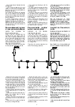
Régulation
– Le fonctionnement des compresseurs
est sous la dépendance du module
électronique. En fonction de la tempéra-
ture de retour d’eau froide (CIATCOO-
LER) ou d’eau chaude (THERMACIAT),
le module électronique demandera la
marche ou l’arrêt en cascade des com-
presseurs.
La sonde de régulation eau froide ou
eau chaude est placée, dans une confi-
guration standard de l’appareil, sur le
retour d’eau évaporateur (utilisation
froid) ou condenseur (utilisation pompe
à chaleur).
Electronic control and
display module
All of the LG Series units are equipped
with a microprocessor electronic con-
trol and display module.
Models LG, LGN, LGP 100 - 150 - 200
- 250 - 300 are equipped with the
MRS4-2.A module.
Models LG, LGN, LGP 350 - 400 - 450
- 500 - 600 arte equipped with the
MRS1-4.A module.
Principal functions
Water temperature control :
– evaporator chilled water (CIAT-
COOLER).
– condenser hot water (THERMACIAT).
2 types of controls systems are possible
– differential on the water return.
– PIDT on the water outlet.
In standard configuration, these units
have a control system on the chilled
water return (CIATCOOLER) or on the
hot water (THERMACIAT). To obtain
PIDT control on the water outlet temper-
ature, refer to the MRS maintenance
brochures.
Control of operating parameters.
Faults diagnosis.
Memorization of faults in case or cur-
rent cut.
Handling and automatic equalization
of compressors operating time (multi-
compressors).
Possibility of remote control (run/stop,
modification of temperature settings,
operating status and general faults) with
an optional remote controller.
Possibility of remote reporting of oper-
ating status and faults through and inter-
face module (optional).
Possibility of teleprocessing control.
FOR DETAILED DESCRIPTIONS OF
ALL THESE FUNCTIONS, REFER TO
MRS MAINTENANCE BROCHURES.
Control
– Compressor running is controlled by
the electronic module. As a function of
the return cold water temeprature (CIAT-
COOLER) or hot water (THERMACIAT),
the electronic module demands running
or stopping in series of the compres-
sors.
In the standard configuration, the cold or
hot water control sensor is located on
the evaporator water return (cooling
use) or condenser (heat pump use).
Elektronikmodul zur Regelung
und Anzeige
Alle Kaltwassersätze der Serie LG und abgelei
tete Geräte sind mit einem
Elektronikmodul mit
Mikroprozessor MRS
zur Regelung und
Anzeige ausgestattet.
Die Modelle
LG, LGN, LGP 100 150 200 250
300
sind mit einem Elektronikmodul MRS4-2.A
ausgestattet.
Die Modelle
LG, LGN, LGP 350 400 450 500
600
sind mit einem Elektronikmodul MRS1-4.A
ausgestattet.
Hauptfunktionen
Regelung der Wassertemperatur:
- Kaltwasser am Verdampfer (CIATCOOLER)
- Warmwasser am Verflüssiger (THERMACIAT)
Möglichkeit von 2 Regelarten:
- Messung am Wassereintritt
- Temperaturfühler PIDT am Wasseraustritt
Die Geräte sind in der Standardausstattung
mit einem Regelsystem am Kaltwassereintritt
(CIATCOOLER) oder Warmwassereintritt
(THERMACIAT) ausgerüstet. Für eine Regelung
über Temperaturfühler PIDT am Wasseraustritt
siehe die BEDIENUNGSANLEITUNG des MRS.
Kontrolle der Betriebsparameter
Fehlerdiagnose
Speicherung der Fehler bei Stromausfall
Automatische Verwaltung und Betriebsstun
denausgleich des Verdichters (bei mehreren Ver
dichtern)
Fernsteuerung (EIN/AUS, Änderung der Tem
peraturvorgabe, Betriebszustände, allgemeine
Fehleranzeige) über eine Fernbedienung (SON
DERAUSSTATTUNG)
Fernübertragung der Betriebs- und Fehler
zustände über ein Schnittstellenmodul (SON
DERAUSSTATTUNG)
Steuerung über Fernverwaltung (SONDER
AUSSTATTUNG)
FÜR EINE DETAILLIERTE BESCHREIBUNG
DIESER FUNKTIONEN SIEHE DIE BEDIE
NUNGSANLEITUNG ZUM MRS.
Regelung
- Der Betrieb der Verdichter hängt vom Elektro
nikmodul ab. Je nach der Temperatur des
rückgeführten Kaltwassers (CIATCOOLER)
oder Warmwassers (THERMACIAT) steuert das
Elektronikmodul stufenweise das Einschalten
bzw. Abschalten der hintereinandergeschalteten
Verdichter.
Der Kalt- und Warmwasserfühler ist bei der Stan
dardausführung des Geräts in der Wassereintritt
sleitung des Verdampfers (bei Kühlbetrieb) bzw.
des Verflüssigers (bei Einsatz der Wärmpumpe)
angebracht.