CIAS Elettronica S.r.l.
Ed. 1.2
Installation Handbook
Page
60
of
73
ERMO 482X3
PRO
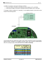
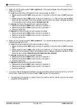
In addition it’s possible to manage the following conditions:
•
Line cut condition of the wires connecting the external detector at TX or RX PCB
•
Short Circuit condition of the wires connecting the external detector at TX or RX PCB
To manage all these con
ditions it’s necessary to use weighting resistors connected like that
showed in the following picture.
In the following table are indicated the voltage values present at balanced inputs for the possible,
detector and line, conditions. It is possible to read this values, also by means of WAVE-TEST2
SW in the “Analogue values” window.
(PC in local or remote connection)
0
-
0.5
LINE SHORT CIRCUIT
CONDITIONS
INPUT VOLTAGE
[V dc]
LINE CUT
FAULT
TAMPER
ALARM
REST
0.5
1
1.5
1.5
2
2.5
2.5
3
3.5
3.5
4
4.5
4.5
-
5
Min. Average Max.

