CIAS Elettronica S.r.l.
Ed. 1.2
Installation Handbook
Page
51
of
73
ERMO 482X3
PRO
3 CONNECTIONS
3.1 Terminal Blocks, Connectors and Circuits Functions
3.1.1 Transmitter Circuit
Figure 9
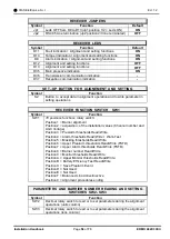
Layout of connectors, jumpers, LEDs and presetting in transmitter board
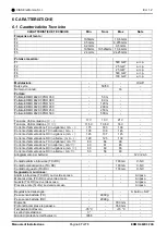
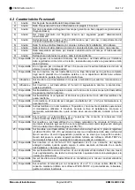
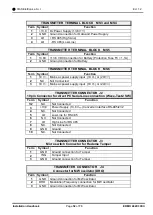
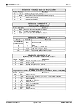
The following tables shows the connector pin functions present on ERMO 482X3
PRO
Transmitter
TRANSMITTER TERMINAL BLOCK MS1
Term Symbol
Function
1
GND
Ground connection for sync cable
2
SYNC Sync In/Out connection to perform Slave/Master operation
setting JP1
TRANSMITTER TERMINAL BLOCK MS2
Term Symbol
Function
1
ALL 1
Alarm relay contact (Normally Closed)
2
ALL 2
Alarm relay contact (Normally Closed)
3
PT 1
Tamper relay contact (Normally Closed) + bulb contact (AMP1)
4
PT 2
Tamper relay contact (Normally Closed) + bulb contact (AMP1)
5
GST 1 Fault relay contact (Normally Closed)
6
GST 2 Fault relay contact (Normally Closed)
7
ST BY Auxiliary input for Stand-By command (Norm. Open from GND)
8
TEST
Auxiliary input for Test command (Norm. Open from GND)
9
GND
Ground auxiliary connection
10
ING
Balanced Line Input for external device (detector)

