9
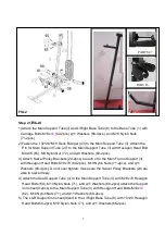
Step 2
(
((
(FIG.2)
FIG.2)
FIG.2)
FIG.2)
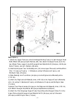
1)Attach the Main Support Tube(3) and L/Right Base Tube (8) to the Base Tube (1) with
Carriage Bolts M10x
80
(62-2pcs)
φ
11 Washers (68-4pcs), and M10 Nylon Nuts
(71-2pcs).
2)Fasten the
∮
32*26*M10 Deck Bumper (43) to the Main Support Tube (3). Attach the
Pin for Main Support Tube (27) to the Main Support Tube (3) with Hexagon Head Bolt
M8x45 (65), M8 Nylon Nut (72), and
φ
9 Washers (69-2pcs).
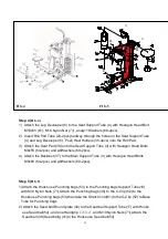
3) Attach Swivel Pulley Brackets (24-2pcs) to each of to the Main Frame Support (3)
with Hexagon Head Bolts M10x70 (60-2pcs), M10 Nylon Nuts (71-2pcs), and
φ
11
Washers (68-4pcs). Do not over tighten; make sure the Swivel Pulley Brackets (24) are
able to swivel freely.
4) Attach the Seat Support Tube (4) to the Main Support Tube (3) with M10x70 Hexagon
Head Bolts (60), M10 Nylon Nuts (71), and
φ
11 Washers (68-2pcs).attach the Support
iron sheet(9-2pcs) to the Main Support Tube (3) with Hexagon Head Bolts M10x
80
(62), M10 Nylon Nuts (71), and
φ
11 Washers (68-2pcs).
5) The L&R Support iron sheet(9)and to the L/Right Base Tube (8) with 10×20 Hexagon
Head Bolts(58-2pcs) M10 Nylon Nuts (71), and
φ
11 Washers(68-2pcs)
PARTS 27
PART 16
FIG.2
Содержание CD-2006A
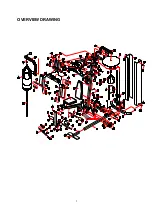
Страница 4: ...3 OVERVIEW DRAWING...


