background image

2.

Dress properly.  Do not wear loose clothing or jewelry.  Contain long hair.
Keep your hair, clothing, and gloves away from moving parts.

  Loose

clothes, jewelry, or long hair can be caught in moving parts.

3.

Avoid accidental starting.


Be sure the Power Switch is off before plugging

in. 

 Plugging in power tools with the Power Switch on invites accidents.

4.

Remove adjusting keys or wrenches before turning the power tool on.  

A

wrench or a key that is left attached to a rotating part of the power tool may result
in personal injury.

5.

Do not overreach.  Keep proper footing and balance at all times. 

 Proper

footing and balance enables better control of the power tool in unexpected
situations.

6.

  Always wear eye, hearing, breathing protection, and heavy duty
  work gloves. 

 Wear ANSI approved safety impact goggles, ANSI ap-

  proved hearing protectors, ANSI approved dust mask or respirator, and
  heavy duty work gloves when using this product.  Also, non-skid safety
  shoes and a hard hat must be used for appropriate conditions.

TOOL USE AND CARE

1.

Do not force the tool.  Use the correct tool for your application. 

 The correct

tool will do the job better and safer at the rate for which it is designed.

2.

Do not use the power tool if the Power Switch or Safety Shut-Off Switch
does not turn it on or off.

  Any tool that cannot be controlled with the Power

Switch or Safety Shut-Off Switch is dangerous and must be replaced.

3.

  Disconnect the Power Cord Plug from the power source before
  making any adjustments, changing accessories, or storing the tool.

  Such preventive safety measures reduce the risk of starting the tool
  accidentally.

4.

Store idle tools out of reach of children and other untrained persons.  

Tools

are dangerous in the hands of untrained users.

5.

Maintain tools with care.  Keep tools clean.

  Properly maintained tools are

easier to control.  Do not use a damaged tool.  Tag damaged tools “Do not use”
until repaired.

SKU 92281      

For technical questions, please call 1-800-444-3353.


PAGE 4

6.

Check for misalignment or binding of moving parts, breakage of parts, and

Содержание 92281

Страница 1: ...ght 2004 by Harbor Freight Tools All rights reserved No portion of this manual or any artwork contained herein may be reproduced in any shape or form without the express written consent of Harbor Freight Tools For technical questions please call 1 800 444 3353 TO PREVENT SERIOUS INJURY READ AND UNDERSTAND ALL WARNINGS AND INSTRUCTIONS BEFORE USE Model 92281 ...

Страница 2: ...arts Lists on page 16 are included If any parts are missing or broken please call Harbor Freight Tools at the number shown on the cover of this manual as soon as possible IMPORTANT SAFETY INSTRUCTIONS Item Description Electrical Requirements 115 V 60 Hz 2000 Watt 4 15 AMPs No Load 5 20 AMPs With Load 2 5 HP Single Phase 3460 RPM 3 Prong Power Plug Power Cord Length 15 Power Switch Type ON OFF Slid...

Страница 3: ...f electric shock 4 Do not abuse the Power Cord Never use the Power Cord to pull the Plug from an outlet Keep the Power Cord away from heat oil sharp edges or moving parts Replace damaged Power Cords immediately Damaged Power Cords increase the risk of electric shock 5 When operating a power tool outside use an outdoor extension cord marked W A or W These extension cords are rated for outdoor use a...

Страница 4: ...uct Also non skid safety shoes and a hard hat must be used for appropriate conditions TOOL USE AND CARE 1 Do not force the tool Use the correct tool for your application The correct tool will do the job better and safer at the rate for which it is designed 2 Do not use the power tool if the Power Switch or Safety Shut Off Switch does not turn it on or off Any tool that cannot be controlled with th...

Страница 5: ...ING WARNING Improperly connecting the grounding wire can result in the risk of electric shock Check with a qualified electrician if you are in doubt as to whether the outlet is properly grounded Do not modify the power cord plug provided with the tool Never remove the grounding prong from the plug Do not use the tool if the power cord or plug is damaged If damaged have it repaired by a service fac...

Страница 6: ...cord 2 As the distance from the supply outlet increases you must use a heavier gauge extension cord Using extension cords with inadequately sized wire causes a serious drop in voltage resulting in loss of power and possible tool damage See Figure B next page 3 The smaller the gauge number of the wire the greater the capacity of the cord For example a 14 gauge cord can carry a higher current than a...

Страница 7: ...ion cords from sharp objects excessive heat and damp or wet areas V A no xxxx min No Load Revolutions per Minute RPM Amperes Volts Alternating Current Underwriters Laboratories Inc Canadian Standards Association Double Insulated SYMBOLOGY FIGURE C RECOMMENDED MINIMUM WIRE GAUGE FOR EXTENSION CORDS 115 VOLT NAMEPLATE AMPERES At Full Load EXTENSION CORD LENGTH 25 FEET 50 FEET 75 FEET 100 FEET 150 FE...

Страница 8: ...expelled from the Chute at a very high rate of speed and can cause severe personal injury 6 Check the Hopper 1 Body 13 and Chute 32 for debris Before plugging in the Chipper Shredder make sure the Hopper Body and Chute are empty Make a visual check and or push the end of the Feed Stick 59 around the inside of the Hopper Body and Chute Make sure to remove all debris 7 Inspect the material before in...

Страница 9: ...als safely away while operating the Chipper Shredder 21 For your safety In extreme working conditions sensors in the Chipper Shredder will automatically switch off the Motor to prevent overheating In this event turn the Power Switch 47 to its OFF position Unplug the electrical cord and wait five minutes or until the Motor has cooled Clear the machine of all debris Plug in the electrical cord and d...

Страница 10: ...ia Health Safety Code 25249 5 et seq 27 WARNING People with pacemakers should consult their physician s before using this product Operation of electrical equipment in close proximity to a heart pacemaker could cause interference or failure of the pacemaker 28 WARNING The warnings and cautions discussed in this manual cannot cover all possible conditions and situations that may occur It must be und...

Страница 11: ...If not already installed insert all three Safety Nuts 8 into the slots in the Hopper 1 from the inside so that their round ends are inside the Hopper 1 See Figure E 2 Place the Hopper 1 into the Body 13 lining up the Safety Nuts 8 with the slots in the Body Secure the Hopper in place using Washers 9 10 and Screws 11 3 Close the Body 13 and tighten the Knob 7 firmly to secure it in place See Figure...

Страница 12: ...de of the Motor Support 26 using two Screws 27 two Washers 34 and two Lock Nuts 33 See Figure F LEFT SIDE VIEW RIGHT SIDE VIEW RIGHT SUPPORT LEG 35 LEFT SUPPORT LEG 61 MOTOR SUPPORT 26 SCREW 27 WASHER 34 LOCK NUT 33 SCREW 27 WASHER 34 LOCK NUT 33 FIGURE F 4 Assemble the Wheel Axle assemblies using the parts shown below See Figure G WHEEL COVER 21 SCREW 22 WASHER 36 BUSHING 37 WHEEL 38 WASHER 36 SC...

Страница 13: ...anches into the Chipper Shredder 6 Do not force the Chipper Shredder Let the natural suction process take in the material to be cut Always stand clear and to the side of the Chute 32 See Figure H 7 Without putting your hands into the Hopper 1 slowly drop the material in one branch at a time The machine will pull it in automatically 8 WARNING Never use your hands to feed material into the Hopper 1 ...

Страница 14: ... the Chipper Shredder turn the Power Switch 47 to its OFF position Unplug the Power Cord 58 from its extension cord Then unplug the extension cord from its electrical outlet See Figure H 13 Wait until all moving parts on the Chipper Shredder have stopped moving Then open the unit and clean out the Hopper 1 Body 13 Motor Support 26 and Chute 32 See Figure H 14 Make sure to store the Chipper Shredde...

Страница 15: ...l cause excessive wear on the Motor and will cause jamming Reverse or sharpen the Blades when needed When reversing Blades always wear heavy duty gloves to avoid accidental cuts to hands and fingers To reverse the Blades remove the four Screws 14 that secure the Blades to the Disc 19 Turn the Blades over to expose the sharp edges Then retighten the Screws to secure the Blades to the Disc See Figur...

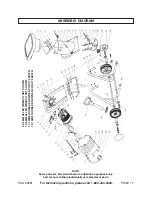
Страница 16: ...LACEMENT PARTS THERETO Part Description Q ty Part Description Q ty 1 Hopper 1 37 Bushing 2 2 Hopper Flap 1 38 W heel 2 3 Press Board 1 39 Screw 7 4 Screw 7 40 W asher 3 5 Cover 1 41 Switch Shelf 1 6 Nut 1 42 Safety Shut O ff Switch 1 7 Knob 1 43 W ire A 2 8 Safety Nut 3 44 M otor Assem bly 1 9 W asher 3 45 Covering 1 10 W asher 11 46 W ire B 2 11 Screw 3 47 Power Switch 1 12 Bolt 1 48 W ire D 1 13...

Страница 17: ...44 3353 PAGE 17 NOTE Some parts are listed and shown for illustration purposes only and are not available individually as replacement parts 69 5MM ALLEN WRENCH NOT SHOWN 70 6MM ALLEN WRENCH NOT SHOWN 71 13MM DOUBLE END WRENCH NOT SHOWN 72 16MM DOUBLE END WRENCH NOT SHOWN ...

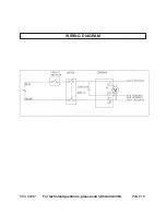
Страница 18: ...WIRING DIAGRAM SKU 92281 For technical questions please call 1 800 444 3353 PAGE 18 ...

Отзывы: