manualshive.com logo in svg
background image

OWNER

’S

 MANUAL

ENGLISH

PN: 72727-00 

Rev. 040918 

Companion to 72728-00 

Range: 5VJAA0412JW005859 - Current

CH611DH –

 1.1 L Diesel Kubota

®

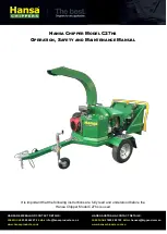
6 INCH CHIPPER

bearcatproducts.com

Содержание BearCat CH611DH

Страница 1: ...OWNER S MANUAL ENGLISH PN 72727 00 Rev 040918 Companion to 72728 00 Range 5VJAA0412JW005859 Current CH611DH 1 1 L Diesel Kubota 6 INCH CHIPPER bearcatproducts com ...

Страница 2: ...products com service bearcatproducts com Monday Friday 8 a m to 5 p m Central Time 2018 CRARY INDUSTRIES ALL RIGHTS RESERVED PRODUCED AND PRINTED IN THE U S A FOR MACHINE SERVICE OR PARTS For service assistance contact your nearest authorized ECHO Bear Cat dealer or the factory For parts contact your authorized dealer The parts manual for your machine is available at bearcatproducts com Product Su...

Страница 3: ...normal wear items including but not limited to batteries bearings belts pulleys filters chipper blades shredder flails or knives 3 This warranty does not cover normal maintenance service or adjustments 4 This warranty does not cover depreciation or damage due to misuse negligence accident or improper maintenance 5 This warranty does not cover damage due to improper setup installation or adjustment...

Страница 4: ... 4 3 CHIPPER OPERATION GUIDELINES 16 4 4 SLOWING AND STOPPING THE CHIPPER ROTOR AND ENGINE 17 4 5 FEED ROLLER SPEED CONTROL 17 4 6 CHIPPER FEED CONTROLLER 17 4 7 USING THE DIGITAL DISPLAY CONTROLLER 18 4 8 TOWING 20 5 SERVICE MAINTENANCE 21 5 1 MAINTENANCE SCHEDULE 21 5 2 ROTOR LOCK 22 5 3 RAISE LOWER ACCESS COVER 22 5 4 CHIPPER BLADES MAINTENANCE 22 5 5 REMOVING THE BLADES 23 5 6 SHARPENING THE B...

Страница 5: ...t caught in the machine 6 Do not operate this machine if you are under the influence of alcohol medications or substances that can affect your vision balance or judgement Do not operate if tired or ill You must be in good health to operate this machine safely Federal state and local laws may prohibit the operation of an internal combustion engine using hydrocarbon fuels on any forest covered brush...

Страница 6: ...roper balance and footing at all times 5 Check cutting chamber to verify it is empty before starting the machine 6 Therotorwillcontinuetorotateafterbeingdisengaged Shut off the machine and make sure all moving parts have come to a complete stop before inspecting or servicing any part of the machine Disconnect the battery and remove the ignition key if applicable 7 Do not insert branches with a dia...

Страница 7: ...e or spark 5 Never store this machine with fuel in the fuel tank inside a building where fumes may be ignited by an open flame or spark Ignition sources can be hot water and space heaters furnaces clothes dryers stoves electric motors etc 6 Drain the fuel and dispose of it in a safe manner for storage periods of three months or more DANGER POISON FLUSH EYES IMMEDIATELY WITH WATER GET MEDICAL HELP ...

Страница 8: ...y cause poor performance damage or personal injury and will void the machine warranty See Section 1 10 for decal locations Familiarize yourself with all of the safety and operating decals on the machine and the associated hazards See the engine owner s manual or contact the engine manufacturer for engine safety instructions and decals PN 12174 Keep hands and feet out of inlet and discharge opening...

Страница 9: ...T Decals 11 14 not for CE compliant machines 1 10 SAFETY DECAL LOCATIONS The numbers below correspond to the decals in Section 1 9 Make certain that all safety and operating decals on this machine are kept clean and in good condition Decals that need replacement must be applied to their original locations 1 2 3 4 5 6 7 8 10 9 11 12 13 14 Decal located under shield Decal located on trailer ...

Страница 10: ...th two M12 100 mm bolts 8 washers nuts and torque to 140 Nm NON CE COMPLIANT FIGURE 2 1 1 Place hitch pole assembly 8 into the frame align mounting holes to desired length and secure using two 1 2 4 1 2 bolts washers and nuts hardware not shown in Figure 2 1 Torque to 75 ft lbs 2 ASSEMBLY Where applicable 1 Remove the chipper from its shipping crate Place the unit on a level surface before attempt...

Страница 11: ...ion 9 Next insert the ends of the brake cable lines 13 in to the outside holes of the balance bar bracket 10 Secure the balance bar bracket to the brake rod by threading the M10 35 mm spherical nut 14 on to the brake rod making sure that the convex end of the nut is toward the bracket This nut will be the adjustment point for setting brake tension 11 Adjust the length of the brake rod so there is ...

Страница 12: ...e feed roller housing For the two lower bolt locations insert the bolts from inside the feed chute The other five bolts mount through the left and right chute supports on the outer flanges of the feed roller housing and feed chute Install one 3 8 1 1 2 carriage bolt 3 clamp 4 and nylock nut as shown Do not tighten completely at this time 2 Bolt the chute support 5 to the chipper frame with two 3 8...

Страница 13: ...n the chipper frame The discharge clamp 1 should slide underneath the lip of the flange Tighten the bolts to secure it 3 Install the second half of the spacer 2 and clamp ring 1 on the discharge tube with 3 8 1 1 4 bolts 4 and nylock nuts 5 2 7 ATTACH DISCHARGE TUBE Figure 2 10 Attach Clamp Ring and Spacer 1 2 3 4 5 Figure 2 11 Attach Discharge Tube 1 2 4 5 6 4 Attach lanyard with discharge pin 6 ...

Страница 14: ...anual or authorized dealer for specification details To install the battery 1 Open the battery box 11 1 8 7 3 4 10 1 8 and insert battery into the battery box 2 Attach the positive red battery cable from the engine to the positive battery terminal 3 Attach the negative black battery cable from the engine to the negative battery terminal 4 Secure the cover on the battery box with the strap Figure 2...

Страница 15: ...omes in contact with hot parts or sparks from ignition Do not start the engine near spilled fuel Never use fuel as a cleaning agent DO NOT MIX OIL WITH FUEL WARNING Use only those types of fuels that are recommended in your engine owner s manual To add fuel 1 Stop engine and wait for all parts to stop moving Remove key from key switch Allow the engine and muffler to cool for at least three minutes...

Страница 16: ...18 19 20 21 23 22 6 24 Understanding how your machine works will help you achieve the best results when using your chipper The following descriptions define the features and controls of your machine REFER TO ENGINE OWNER S MANUAL FOR FURTHER ENGINE OPERATING INSTRUCTIONS CH611DHXE MODEL ...

Страница 17: ...rclockwise will increase the speed of the feed roller 11 HITCH JACK Always have in UP position and clear from ground when moving When in use place in DOWN position on a level surface Turn handle to raise or lower wheel 12 MANUAL CONTAINER Conveniently holds your manuals 13 REAR STABILIZER Prevents the chipper from tipping when disconnected from tow vehicle Always have in UP position and clear from...

Страница 18: ...r prolonged period 2 Check levels of fuel oil and hydraulic fluid and fill if necessary 3 Squeeze the primer bulb located inside the engine compartment 3 4 times 4 Place chipper engagement handle in the START position Open the throttle slightly by turning throttle knob counterclockwise a 1 4 turn 4 2 OPERATING THE CHIPPER To begin operating the chipper follow the steps below 1 AFTER engine is warm...

Страница 19: ...ter the engine starts Warning indicator Figure 4 3 Engine Control Panel Engine speed Low oil pressure Battery indicator High engine temperature Pre heat glow plug button Hour meter display Engine start button Engine speed The rabbit icon is disabled and non functional for use on this chipper Fail to Start If the engine does not fire after the pre set 3 attempts at starting a shutdown will be initi...

Страница 20: ...llowing guidelines will help you get started 1 Gradually increase engine speed until full throttle is achieved When the controller light is steady green the engine speed is high enough to begin to chip 2 ALWAYS run engine at full operating speed before starting to chip material 3 Engage the hydraulic feed by pushing the forward button from the Chipping Screen see Section 4 7 for more details on ut...

Страница 21: ...with the engine shutting off TO PROPERLY SLOW DOWN AND STOP THE ROTOR AND ENGINE 1 With the belt still engaged unlock the throttle and SLOWLY turn clockwise until engine reaches slow idle speed 2 Allow the engine to run at slow idle for 30 60 seconds 3 Turn the key to the OFF position 4 Allow rotor to come to a complete stop 4 6 CHIPPER FEED CONTROLLER This machine is equipped with a Digital Displ...

Страница 22: ...Controller Manual P N 71983 00 for more information on using the Diagnostics screen to help troubleshoot the chipper control system NOTE The Chipping Screen is accessible from any screen by pressing the Chipping Screen button NOTE 4 7 USING THE DIGITAL DISPLAY CONTROLLER The feed roller FORWARD and REVERSE functions are controlled by the controller In addition to the feed roller control functions ...

Страница 23: ...ed image is an empty area of the screen that will flash Check blades anvil when the chipper blades or anvil require service After servicing the blades and anvil the service indicator will need to be reset See Section 4 7 3 for information on resetting the service indicators The large indicator in the upper right hand corner and the text box below it will give one of four indications Flashing Green...

Страница 24: ...e opposite direction of the towing vehicle before towing 2 Raise rear stabilizer 3 Raise the extension tray to an upright position before towing the machine Secure with the spring loaded latch located near the top of the tray 4 Open the coupler latch 5 Raise the trailer hitch until the coupler is above the height of the hitch ball on the towing vehicle 6 Align the coupler over the hitch ball and l...

Страница 25: ...l All internal and external nuts and bolts Check tightness Tire pressure Check Battery connections Check Chipper anvil Check clearance and re torque to 75 ft lbs 2 Chipper blades Check sharpness and re torque to 120 ft lbs 2 Entire machine Clean Drive belt Check Hydraulic drive belt Check Belt tension Check Belt pulley alignment Check Grease zerks Lube Hydraulic oil filter Replace Wheel bearings C...

Страница 26: ...en corners or nicks greater than 1 8 see below The base of the cutting edge is worn or has been re sharpened so that it no longer extends past the chipping slot see below 5 2 ROTOR LOCK Follow the steps below to install the rotor lock 1 Open the rotor access cover 2 Rotate the rotor assembly until the hole on the rotor lines up with the matching hole on the rotor housing 3 Install pin through hole...

Страница 27: ...emove the two 3 8 retaining bolts securing the access cover to the main frame assembly 2 Open access cover to allow access to rotor Rotate the rotor so that the bolts holding the chipper blades are accessible 3 Install the rotor lock Section 5 2 The rotor is now restrained for removing the blades To access the remaining blades remove pin and reposition rotor Return pin to the rotor lock hole 4 Rem...

Страница 28: ...ts on chipping anvil to 75 ft lbs and resume operation 6 If chipping anvil edge is damaged or worn unevenly remove the three bolts holding the anvil and use one of the other three edges Adjust for correct measurement When all four edges have been used replace anvil CHIPPING ANVIL SPACER HOUSING Figure 5 4 Chipping Anvil Location 5 8 SETTING CHIPPER BLADE CLEARANCE ROTOR CHIPPER BLADE ANVIL ANVIL S...

Страница 29: ... deflection at the center of the belt should be 7 16 with a 20 lb load If necessary adjust spring tension 11 Shut engine hood Feeding too large or too much material at once may plug the chipper To clear a plugged rotor proceed as follows 1 Lift the engagement handle and turn off engine key switch Allow all moving parts to come to a complete stop 2 Remove the two 3 8 retaining bolts holding the acc...

Страница 30: ... rotor 3 Follow Section 5 11 1 to remove drive belt 4 Remove the bolts attaching the pulley bushing to the pulley 5 Install the bushing push bolts and tighten alternately one flat at a time to remove the bushing from the pulley 6 Remove the pulley and the pulley bushing 7 Remove bearing cap and bearing lock 8 Loosen both bearing set screws on each bearing 9 Remove four bearing mounting bolts on ea...

Страница 31: ...reservoir level Add fluid if necessary The hydraulic pump is now ready for operation 5 13 HYDRAULIC FEED MAINTENANCE Check the oil level before each use Change oil as directed in the engine owner s manual Handle pressurized hydraulic fluid carefully Escaping pressurized hydraulic fluid may penetrate your skin causing serious injury This fluid may also be hot enough to burn Serious infection or rea...

Страница 32: ... conditions will require more frequent greasing Grease the following points every 50 100 hours of operating time Two bearings on the drive shaft One grease zerk on bearing assembly One grease zerk on the discharge tube base Do not over grease bearings Overfilling can lead to excessive heat and or unseating of the seals Add grease slowly and under light pressure Whenever possible rotate bearing slo...

Страница 33: ...pper has not reached chipping RPM upon initial startup Slowly increase RPM 1 2 second on 1 2 second off Chipper RPM dropped while chipping Feed roller will automatically pause to bring RPM back up RED Solid Knee bar was activated Hold Knee Bar Reset Solid Battery voltage is low Charge battery Check charging system YELLOW Solid Controller has detected an electrical system fault Use diagnostics scre...

Страница 34: ...ion too loose Adjust tensioner Replace belt if needed Machine chips poorly Dull chipper blades Flip sharpen or replace Drive belts loose or worn Inspect drive belts adjust or replace if needed Feeding material that is too large Limit branch size to rated capacity Cannot engage belt Improper belt installation belt not under belt guide Install belt properly install belt under belt guide Improper bel...

Страница 35: ...irm that PTO is 540 RPM Knee bar sensor does not stop feed roller Knee bar linkage is not free to move Check knee bar linkage for full range of motion Harness connection or sensor failure Check harness connection Adjust or replace sensor Feed roller alternates between forward and reverse Hydraulic motor is malfunctioning Hydraulic motor needs to be replaced Pressure switch fault Unhook the pressur...

Страница 36: ...ters Maximum Chipper Capacity 6 diameter 15 2 cm diameter Chipper Blades 4 reversible 5 4 0 5 4 reversible 12 7 cm 10 2 cm 1 3 cm Chipping Anvil 4 edge adjustable 6 5 4 0 625 4 edge adjustable 16 5 cm 10 2 cm 1 6 cm Rotor Size 26 diameter 1 66 cm diameter 2 5 cm Rotor Speed 1780 RPM Rotor Weight 165 lbs 75 kg Discharge Tube Size 6 15 2 cm Discharge Tube Height 97 246 cm Jack 1000 lb rating 454 kg ...

Страница 37: ...ues by 5 BOLT DIAMETER A BOLT TORQUE SAE 2 SAE 5 SAE 8 NM FT LB NM FT LB NM FT LB 1 4 7 5 5 5 11 8 16 12 5 16 15 11 23 17 34 25 3 8 27 20 41 30 61 45 7 16 41 30 68 50 95 70 1 2 68 50 102 75 149 110 9 16 97 70 149 110 203 150 5 8 122 90 203 150 312 230 3 4 217 160 353 260 515 380 7 8 230 170 542 400 814 600 1 298 220 786 580 1220 900 1 1 8 407 300 1085 800 1736 1280 1 1 4 570 420 2631 1940 2468 182...

Страница 38: ... CHIPPER SPECIFICATIONS 7 2 TEMPERATURE OPERATING WINDOW For the nearest Mobil lubricant supplier or technical information including lubricant information for severe arctic operating conditions call 800 662 4525 ...

Страница 39: ...0 00 2 5 16 Coupler Kit 14519 00 Spare Tire Kit 75291 00 PART NUMBER DESCRIPTION 14519 00 COUPLER 2 5 16 20 000 LB 14900 00 HITCH PINTLE RING 20 000 LB 33900 00 DSE KEY 71930 00 KIT 6 LOW PROFILE DISCHARGE 75291 00 KIT SPARE TIRE 76196 00 KIT 6 IN SAFETY BAR 76293 00 KIT CHIPPER BLADE 1 2 INCH 76722 00 KIT BATTERY DISCONNECT ...

Страница 40: ...ECHO Bear Cat bearcatproducts com 237 NW 12th Street West Fargo ND 58078 0849 Phone 701 282 5520 Toll Free 888 625 4520 Fax 701 282 9522 E mail service bearcatproducts com sales bearcatproducts com ...

Отзывы: