


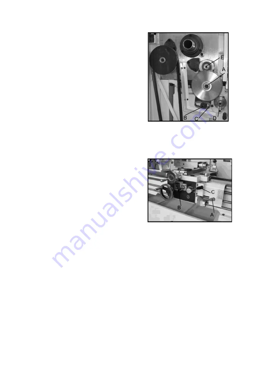
5.
Remove the hex socket cap screws (D
and/or E, Fig18) depending on the which
gear is being changed.
6.
Install the new gear(s) and tighten into
place with a hex socket cap screw.
7.
Loosen the nut (B, Fig 18) and move the
quadrant back so that the teeth mesh on
the gears and tighten the nuts (A and B).
Caution:
Make sure that the is a backlash of
0.002” -0.003” between the gears, setting
the gears too tight will cause excessive noise and wear.
8.
Close the door and
connect the machine to the power source.
Automatic Feed Operation and Feed Changes
1.
Move the forward/reverse selector (A, Fig
19) up or down depending on the required
direction.
2.
Set the selectors (A, B, C and D, Fig 20) to
the desired rate.
Note:
for feeding, lever D will be set at “F” or
“D” depending on the desired feed rate.
Powered Carriage Travel
1.
Push the lever (D, Fig
19) to the left and down to engage the cross feed.
2.
Pull the lever to the
right and up to engage the longitudinal feed.
17
Содержание Voyager Lathe
Страница 19: ...Inch Lead and Feed Table Compound Rest 19...
Страница 25: ...Parts List and Diagrams Headstock Assembly I 25...
Страница 26: ...No Part No Description Size Qty 26...
Страница 29: ...Headstock Assembly II 29...
Страница 32: ...Headstock Assembly III 32...
Страница 35: ...Gearbox Assembly I 35...
Страница 38: ...Gearbox Assembly II 38...
Страница 41: ...Apron Assembly I 41...
Страница 43: ...Apron Assembly II 43...
Страница 45: ...Saddle and Cross Slide Assembly 45...
Страница 48: ...Top Slide and Tool Post 48...
Страница 50: ...Tailstock Assembly 50...
Страница 52: ...Bed and Shaft Assembly 52...
Страница 55: ...Stand and Brake Assembly 55...
Страница 57: ...48 GH1440A 01723 Cover 1 49 GH1440K 22701A Brake Pedal 1 50 GH1440K 22717 Stand Front 1 57...
Страница 58: ...End Gear Assembly 58...
Страница 62: ...Steady Rest 62...
Страница 64: ...Electrical Components 64...