9
TO ADJUST SETTING:
1. Connect tool to air hose with a minimum of 90 psi and remove pulling head and
sleeve cap (1).
2. Screw small end of setting gage (680A159) onto head piston (14) until hand-tight.
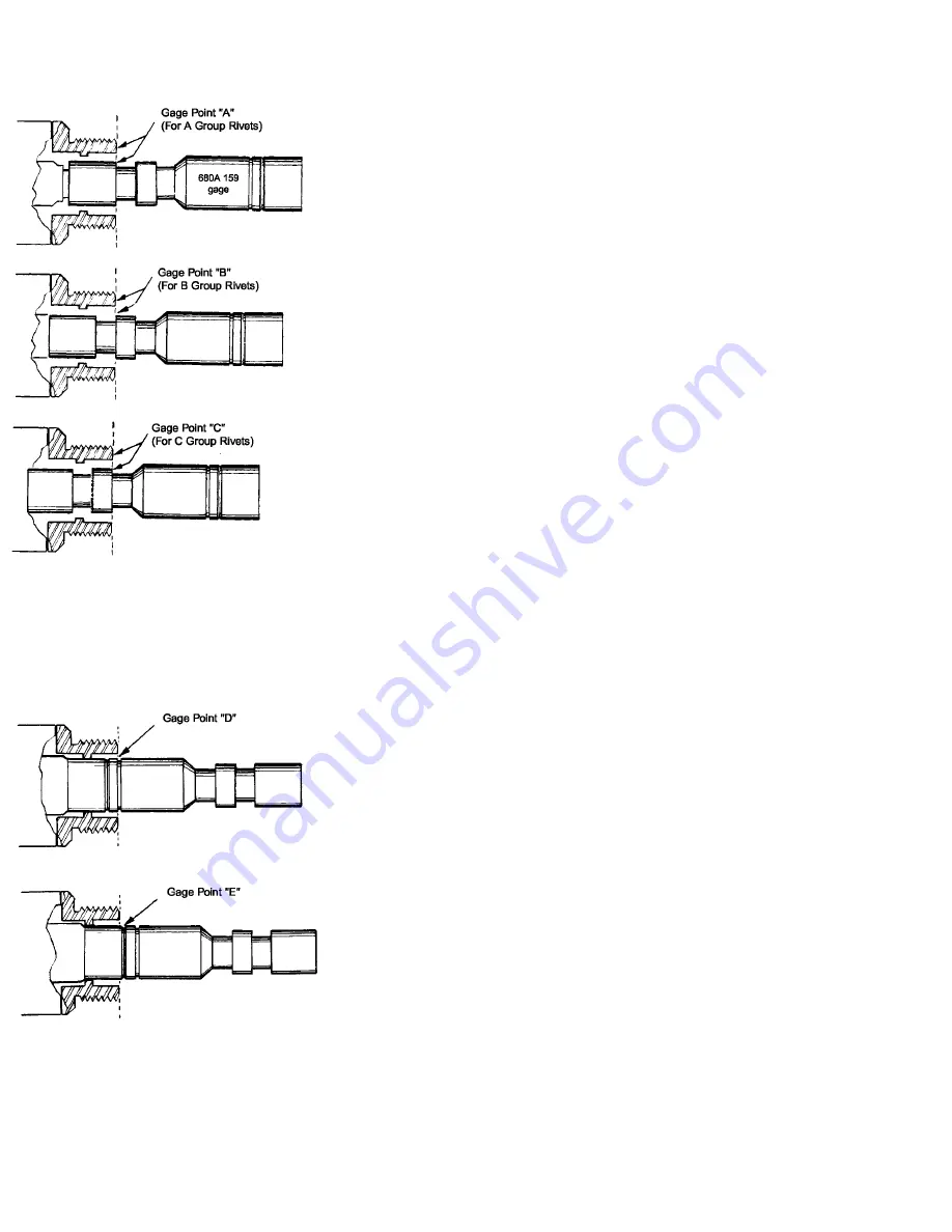
3. Cycle tool and hold trigger so that the gage is pulled into the tool head. Gage Point
“A” should be flush with the front of tool head as shown in the sketch.
4. Release the trigger and turn the adjuster knob (36) clockwise to
increase gage protrusion or counterclockwise to decrease gage
protrusion. Cycle the tool after each adjustment and check the gage
point until it lines up flush with the tool head. A limit pin (34) restricts
adjustment to one-half turn of the knob in either direction from the
factory setting.
Note:
The above procedure will adjust the tool to install “A” group rivets properly. When
“B” group rivets are to be installed, adjust the head as above, and then turn the adjuster
knob (36), six turns counterclockwise. (To turn the shift point adjusting screw more than 1
turn, remove the limit pin (34) and then replace it approximately diametrically opposite
the adjuster knob.) Gage point “B” should be flush with the front of tool head as shown in
sketch. When “C” group rivets are to be installed, again follow the outlined procedure and
then turn the adjuster knob (36) 12 turns counterclockwise. Gage point “C” should now be
flush with the front of tool head as shown in sketch.
CAUTION:
Always release the tool trigger before turning knob and never back off more
than 12 turns or the shift screw (26) may become disengaged from the shift stop (22)
requiring a complete disassembly of the head to replace.
S H I F T P I S T O N C H E C K
The shift piston check is made to ascertain that the movement of the piston is not restricted in any manner. It must be free to
move the amount indicated below in order to obtain proper installation.
1.
Connect the tool to an air hose with a minimum of 90 psi and remove the pulling
head and sleeve cap (1).
2. Insert the large (unthreaded) end of 680A159 gage over the head piston (14) until it
seats in the tool head. With trigger released, the front of the tool head must be
within the gage groove recess, Gage Point “D”, as shown in the sketch.
3.
Cycle the tool and hold the trigger. The gage should move forward at the
completion of the cycle and in this position the single gage line, Gage Point “E”,
must be visible or forward of the front of the tool head as shown in the sketch. The
tool may be cycled while holding the gage in position.
4.
If the gage points do not align, try bleeding the tool. No other
outside adjustments
can be made to correct any deviations from the above gage positions. Failure of
the tool to comply with these gage relationships indicates incorrect tool
performance and it should be sent to the CHERRY® Service
Department for
correction.
Содержание G-689
Страница 13: ...11 CROSS SECTION DRAWING G689...
Страница 15: ...13 EXPLODED VIEW OF G689...


