background image

10

Operations

Product Manual - VaporMan 125

®

 Manifold Vaporizer System

Connecting to the VaporMan 125 

Unit

The VaporMan 125 unit is shipped with caps on the four 

ports on the manifold  If you are using two tanks, you will 

need to remove all four caps  If you are only using one tank, 

only remove the left two caps or the two right caps  The 

transfer hoses that come with the unit can now be connected 

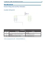
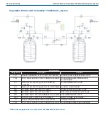
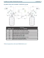
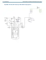
to their proper ports. The diagrams in the Specifications 

section of this manual tell which connections match between 

the VaporMan 125 unit and the tanks  The economizing 

connections on the tanks should be connected to the two top 

ports on the VaporMan 125 unit  Each of these connections 

are 5/8” flared fittings that will mate to the transfer hoses. 

The gas use connections on the tanks should be routed to the 

bottom two connections on the manifold  Tighten each end of 

each hose with a wrench  Check for leaks before pressurizing 

the system 

For a Carbo-Max

®

 1000 Bulk CO

2

 System the pressure 

building circuits must be connected  This allows the tanks 

to equalize their head spaces  This is an integral part in the 

success of this set-up  If the head spaces are not connected 

the tanks may not distribute CO

2

 to the VaporMan 125 unit 

equally 

The check valves are in place to prevent any back flow 

into each tank  The check valves also ensure that the tanks 

equalize and feed the VaporMan 125 system equally 

Delivering CO

2

 to the VaporMan 125 

System

Once the connections are tightened and the entire unit has 

been leak checked, the VaporMan 125 system can now be 

used  A regulator should be placed on the downstream side 

of the VaporMan 125 unit to reach the desired delivery 

pressure to your particular application  The regulator can 

be connected to the VaporMan 125 unit or placed further 

downstream to take advantage of more vaporization  The 

final line regulator from one of the tanks may be used, or the 

high flow regulator PN 11779806 can be ordered from Chart 

Parts 

The VaporMan 125 system has no isolation valves, therefore 

the system is operated by opening all of the isolation valves 

on each tank  The economizing circuit, gas use circuit, and 

the pressure building circuit (for Carbo-Max 1000 tank) 

should all be opened on each tank  The VaporMan 125 unit 

will function as an extension of the tanks and will provide 

vaporized CO

2

 for your application 

Caution!  Once the isolation valves on the 

tank have been opened pressure 

should be allowed to escape from 

the transfer hoses before they 

are completely removed.

Содержание VaporMan 125

Страница 1: ...Part Number 20749848 Rev B 2018 Chart Inc Designed and Built by Chart Inc 407 7th Street NW New Prague MN 56071 USA 800 400 4683 Product Manual VaporMan 125 Manifold Vaporizer System...

Страница 2: ......

Страница 3: ...ow Regulator 6 Operations 7 Initial Inspections 7 Filling Procedures 7 Installing the VaporMan 125 Unit 7 Plumbing Procedures 8 Carbo Max 1000 Bulk CO2 System Parts to be Added 8 Carbo Max 1000 Bulk C...

Страница 4: ...aporMan 125 Unit with Carbo Max 750 Bulk CO2 System 19 VaporMan 125 Unit with Carbo Max 1000 Bulk CO2 System 19 VaporMan 125 Unit with Perma Cyl MicroBulk Storage System 20 Warranty 21 Warranty Policy...

Страница 5: ...ls and kits provided by Chart This manual contains information regarding the safe operation and handling of liquid carbon dioxide with the cylinder and the vaporizer manifold system It should be thoro...

Страница 6: ...f a condition that can result in equipment or component damage Note A statement that contains information that is important enough to emphasize or repeat Acronyms Abbreviations The following acronyms...

Страница 7: ...ith liquid CO2 cold pipes and equipment or cold gas exists Safety goggles or a face shield should be worn at all times when connecting to fill connections while filling the tank and during disconnecti...

Страница 8: ...Monitoring Systems The Analox 50 and Ax 50 Carbon Dioxide Analyzers are precision instruments that provide continuous accurate monitoring of CO2 levels to ensure a safe working environment for your em...

Страница 9: ...a plug and play assembly The vaporizers are connected in a specific order and the vaporizer selection was intentional The parallel vaporizer is used to vaporize the liquid into cold gas The gas is th...

Страница 10: ...bo Max 1000 Bulk CO2 System tanks or who have one Perma Cyl MicroBulk Storage System tank there are two optional kits that will need to be purchased as well The kit names are KIT CARBOMAX VAPORMAN 100...

Страница 11: ...ns A place that has circulation is recommended to aid in melting the ice that might build up on the vaporizers during operation The VaporMan 125 unit will then need to be connected to the tank or tank...

Страница 12: ...in the following illustrations you will remove the Economizing sections Gas Use sections and the Pressure Building sections The parts to be reused are shown on top as well as the parts to be added Car...

Страница 13: ...9 Operations Product Manual VaporMan 125 Manifold Vaporizer System Carbo Max 750 Bulk CO2 System Parts to be Added Carbo Max 750 Bulk CO2 System Parts to be Removed...

Страница 14: ...not connected the tanks may not distribute CO2 to the VaporMan 125 unit equally The check valves are in place to prevent any back flow into each tank The check valves also ensure that the tanks equal...

Страница 15: ...dy VaporMan 125 system pressure is too low or does not build pressure at a sufficient rate VaporMan 125 unit or system is leaking If the pressure does not build and stays at a setting lower than desir...

Страница 16: ......

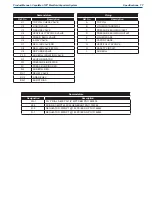
Страница 17: ...re Designation Description Function PG 1 PG 2 DIAL 0 400 PSI 1 4 MPT CBM PN 13321014 PRESSURE GAUGE TANK PRESSURE ECON PRESSURE R 1 REGULATOR 250 NPT 150 PSI ECON PN 13154842 ECONOMIZER REGULATOR RV 2...

Страница 18: ...13154842 ECONOMIZER REGULATOR R 2 REGULATOR 250 NPT 200 PSI SF PN 13154834 SURE FILL REGULATOR RV 1 RV BRS 1 2MPT 300 PSI PN 11708400 PRIMARY SAFETY RELIEF VALVE RV 2 RV BRS 1 2MPT 450 PSI PN 1170845...

Страница 19: ...4 MPT CBM PN 11940305 R 1 REGULATOR 250 NPT 150 PSI ECON PN 13154842 R 2 REGULATOR 250 NPT 200 PSI SF PN 13154834 R 3 REGULATOR 250 NPT 125 PSI PB PN 14743180 RV 1 RV BRS 1 2MPT 300 PSI PN 11708400 R...

Страница 20: ...16 Specifications Product Manual VaporMan 125 Manifold Vaporizer System VaporMan 125 Unit with Perma Cyl MicroBulk Storage System...

Страница 21: ...DICATOR PI 1 PRESSURE INDICATOR R 1 PRESS BUILDING REG R 2 SUREFILL REG RV 1 RELIEF VALVE RV 2 LINE RELIEV BD 1 BURST DISC Piping Ref No Description A TOP FILL B LIQUID WITHDRAWAL C PRESSURE BUILDING...

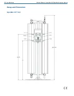
Страница 22: ...18 Specifications Product Manual VaporMan 125 Manifold Vaporizer System Set up and Dimensions VaporMan 125 Unit...

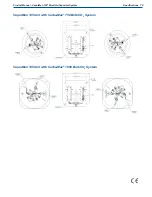
Страница 23: ...19 Specifications Product Manual VaporMan 125 Manifold Vaporizer System VaporMan 125 Unit with Carbo Max 750 Bulk CO2 System VaporMan 125 Unit with Carbo Max 1000 Bulk CO2 System...

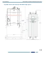
Страница 24: ...20 Specifications Product Manual VaporMan 125 Manifold Vaporizer System VaporMan 125 Unit with Perma Cyl MicroBulk Storage System...

Страница 25: ...fications in any way to the Equipment without Chart s prior written approval shall render this warranty void This limited warranty does not apply to Equipment comprised of materials provided or a desi...

Страница 26: ...Or by writing to Chart Inc 407 7th Street NW New Prague MN 56071 2 Authorization must be obtained from Chart prior to shipping any Equipment to Chart facilities In order to process the return of a tan...

Отзывы: