background image


15

 
Flame Effect    


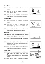
6b.4  Press   to  enter  the  flame  effect  adjustment 

screen.  


6b.5  Press  the  ‘←’  and  ‘→’  bu on  to  select  the  3 

Kinds of flame effect.  


6b.6  Press  the  ‘+’  and  ‘-’  button  to  select  the  5 

brightness of flame effect and OFF settings. 


Fuel Bed Colour 


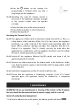
6b.7  Press

to  enter  the  fuel  bed  adjustment 

screen.  


6b.8  Press  the    ‘←’  and    ‘→’    button  to  cycle 

through  the    13  colours  of  fuel  bed  or  a 
colour-cycle mode. 


6b.9  Press the ‘+’ and ‘-’ button to to select the 5 

brightness of fuel bed and OFF settings. 


Mood Light 


Note:  If  mood  lights  are  not  connected,  please  

ensure the brightness is set to zero. 


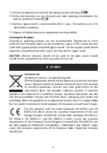
6b.10  Press 

 to  enter  the  mood  light  adjustment 

screen.  


6b.11  Press  the    ‘←’  and  ‘→’    button  to  cycle 

through  the    13  colours  of  mood  light  or  a 
colour-cycle mode. 


6b.12  Press the ‘+’ and ‘-’ button to to select the 5 

brightness of mood light and OFF settings. 


Normal Mode


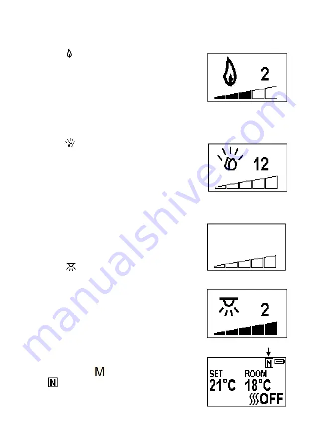
6b.13  Normal control mode is factory set. If it is not, 

then  press 

 button  until  the  logo 

shows up at the upper right corner of the 

screen. 


6b.14  Press  the  ‘+’  and  ‘-’  button  to  adjust  the 

Содержание EF22NC

Страница 1: ...LED Electric Fire Model No EF22NC INSTALLATION AND OPERATION INSTRUCTIONS Please read the instructions carefully before use and keep for future reference ...

Страница 2: ...y Information 1 2 Technical Specifications 3 3 Parts and Hardware 4 4 Appliance Dimensions 6 5 Installation Instructions 6 6 Operating Instructions 12 6a Manual Control Panel 13 6b Remote Controls 14 7 Maintenance 20 8 Others 21 ...

Страница 3: ...ire must not be located immediately below a socket outlet 1 6 This appliance must be earthed 1 7 This appliance must not be supplied through an external switching device such as a timer or connected to the circuit that is regularly switched on and off by utility in order to avoid a hazard due to the inadvertent resetting of the thermal cut out 1 8 A non rewirable plug fitted with a 13A fuse is sup...

Страница 4: ...re in rooms that have explosive gas in them for example petrol or if you are using solvents glue aerosol spray or in flammable paints as these may catch fire 1 14 This appliance can be used by children aged from 8 years and above and persons with reduced physical sensory or mental capabilities or lack of experience and knowledge if they have been given supervision or instruction concerning use of ...

Страница 5: ...n the appliance or perform user maintenance 1 19 This appliance shall not be played with by children 1 20 Children of less than 3 years should be kept away unless continuously supervised 1 21 Keep the power plug accessible after installation 2 TECHNICAL SPECIFICATIONS Model No EF22NC Supply Voltage AC 230 240V 50Hz Maximum power consumption 2KW Power for flame effect 9 5W LED 5 5W Motor for flame ...

Страница 6: ...l with open window detection Yes With distance control option No With adaptive start control Yes With working time limitation No With black bulb sensor No 3 PARTS AND HARDWARE 3 1 Unpacking the fire carefully make sure that the appliance is intact with no signs of damage caused by transport and no part has been exposed to water If in doubt do not use the appliance and contact an authorised service...

Страница 7: ...1set Small Clear Faux Crystal 1set Small Black Faux Crystal 1set G H I Large Clear Faux Crystal 1set Medium Clear Faux Crystal 1set Simplified Manual 1 J K L Remote 1 AAA Battery 2 Instruction Manual 1 M Brackets 4 ...

Страница 8: ...where in your home However when choosing a location ensure that the general instructions are followed 5 1 The appliance should be connected to an earthed electrical outlet and it must be easily accessible to allow disconnection The appliance should be connected to an earthed electrical outlet and it must be easily accessible to allow disconnection 5 2 For best results install out of direct sunligh...

Страница 9: ...FIRE DAMAGE COULD OCCUR IF IT IS NOT FITTED PROPERLY 5 5 The electrical cable may be re routed out of the rear or left side grommet holes of the fire base but the grommet MUST be correctly located in the exit slot to be used 5 6 The product is fitted with a non rewireable plug with a 13Amp fuse Only competent persons should attempt replacement The wires in the mains cable of this appliance are col...

Страница 10: ... the plastic wall plug 5 7c Fit 4 screws ST5 25 onto the arranged holes leaving approximately 2mm space between the wall panel and the screw head 5 7d Lift the engine box onto the screws on the wall panel and make sure the keyhole slots locates on the screw heads 5 7e Tighten the 4 screws to lock the appliance into position 5 7f Put 4pcs magnets with the size of 18 18 12 5 onto the front frame and...

Страница 11: ... installation way the secured spacer needs to be removed from the engine box 5 7g Remove the secured spacer by unfixing the 16pcs screws on both sides of the engine 5 7g Follow the steps from 5 7a to 5 7e for the detailed installation under the 22 opening dimension ...

Страница 12: ...ovided on the plastic shelf Mood Light Strip Connection Note Mood lights are an optional extra Remove the two ST4 10 screws and the metal plate on the right lower side Pull out the cable inside and thread it through the hole of the metal plate Fix the metal plate with two ST4 10 screws and connect the mood light strip various lengths available ...

Страница 13: ... 5 7a to 5 7e for the detailed installation under the 22 opening dimension Put 4pcs magnets with the size of 18 18 12 5 onto the front frame and place the frame with LED strip to the engine Note All the compatible mood lights are available from Charlton Jenrick Ltd and other makes may not be suitable and will void warranty ...

Страница 14: ...unning Use the functions on the remote to turn the fire off and ensure the mains switch has been moved to the off position before disconnecting PREPARATION BEFORE USE 6 1 The appliance can be operated by both remote control and the manual controls on the appliance NOTE To use both remote and manual functions the manual on off switch must be in ON position In order to prevent the product becoming t...

Страница 15: ...the same time 6a 3 Press FLAME button to select the colour of flame 3 kinds or return to the OFF position 6a 4 Press FUEL BED button to select the colour of fuel bed 13 kinds or return to the OFF position NOTE The controls on appliance will lose the memory for all function settings when the switch is set to the Off Position When the remote runs out of power or when you change the batteries only th...

Страница 16: ...e and remote has already been set up If you cannot use the remote with the fire please follow instructions Step 6b37 to initiate this connection in point Standby for Remote Handset 6b 1 The screen shown to the right is when the remote handset is in standby condition Turn on off 6b 2 Press to turn on the flame effect turn off flame effect and heater when in normal mode 6b 3 Press to turn on off the...

Страница 17: ...the and button to to select the 5 brightness of fuel bed and OFF settings Mood Light Note If mood lights are not connected please ensure the brightness is set to zero 6b 10 Press to enter the mood light adjustment screen 6b 11 Press the and button to cycle through the 13 colours of mood light or a colour cycle mode 6b 12 Press the and button to to select the 5 brightness of mood light and OFF sett...

Страница 18: ...de It allows the appliance to go into standby after a set period of time 6b 16 Press to cycle through the settings from Off and 0 5 hours to 9 hours The timer logo and time will show on the screen The heater must be in ON position The heater can be automatically run by using daily timer and weekly timer on the remote Set up Day Time and Comfortable temperature 6b 17 Press to turn on the remote han...

Страница 19: ...e time Minute will increase decrease by 15 minutes per press Hold for 3 seconds or wait for 10 seconds to save and exit the heating time period setting 6b 23 Adjusting the set temperature Press the or button to increase or decrease the temperature on the basis of your comfortable temperature setting ECO means 2 lower than your comfortable temperature setting ECO means 4 lower COMF means 2 higher C...

Страница 20: ...is highlighted or cancel the character is displayed normally the current setting Several days can be selected together Press the bu on to move the cursor to the me period se ng area Press or to choose hour or minute press or to set the number Max 3 heating periods for a day Minute will increase decrease by 15 minutes per press Press the to set the heating time for the selected day s and return to ...

Страница 21: ...t 18 00 Window Open Detection 6b 35 When the transmitter detects a rapid drop in room temperature it will be judged as a window open the warning icon will be displayed and the heating will be turned off automatically 6b 36 After the indoor temperature has risen or a manual override of the warning by operating remote control has been done the fire will return to normal working state Set up the comm...

Страница 22: ...S Control can only be re set after the appliance has cooled down and the appliance has been reset Re setting of the E S Control proceeds is as follows 6b 40 Switch off the appliance Manual On Off switch and leave it off for approximately 10 15 minutes 6b 41 Remove any obstruction to the fan heater outlet or fan blades etc Make sure that the power supply is disconnected with the plug socket outlet ...

Страница 23: ...cal appliances should not be disposed as unsorted municipal waste Separate collection facilities should be used in the disposal of electrical appliances Contact your local government for the information about the available collection systems If electrical appliances are disposed of in landfills or dumps hazardous substances can leak into the groundwater and get into the food chain damaging your he...

Страница 24: ...33 92MHZ Maximum transmit power 10mW Hardware RF290A TX V1 3 Software V2 4 1 Charlton Jenrick Ltd Unit D Stafford Park 2 Telford Shropshire TF3 3AR Tel 0845 5195 991 Fax 0845 5195 992 www charltonandjenrick co uk Hardware RC01 043A02 Software V1 Hardware RF290B V1 2 3 EF 281 05 012 A 0 ...

Отзывы: