


LiPo & LiFe, LiTo Battery Management System BMS24T V4.0
www.chargery.com
page 29 total 41
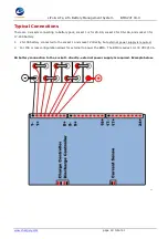
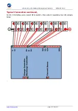
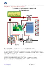
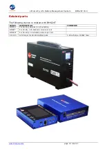
Delay Board Implementation Examples con't.
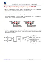
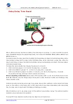
The Small Relay in this example is a simple automotive "Make & Break relay".
The simplest and most
common form of relay. The circuit between terminals 30 and 87 is Closed "on" when energized and Open "off"
when de-energized, this is known as NO (Normally Open). Terminals 85 and 86 actuate the relay. Suggested
to use a 12VDC / 10A or greater relay.
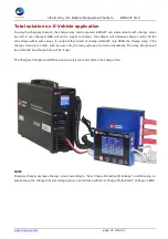
In this configuration, the Discharge relay must be sized to the maximum Amperage anticipated x 1.25.
For example: 24V/4000W Inverter will draw (4000W ÷ 24VDC = 166.66A) X 1.25 = 208.3A
But a Low Frequency Inverter is capable of 3X the wattage (12,000W) for momentary surge. The Charge
relay must be rated for the Maximum Amperage that the charge sources (combined if multiple charge sources)
can output to the battery. For example a Solar Charge Controller at 75A, and an AC Charger at 50A equals a
max input potential of 125A x 1.25 = 156A, so a relay of 150A an up would be suitable.


