


LiPo & LiFe, LiTo Battery Management System BMS24T V4.0
www.chargery.com
page 28 total 41
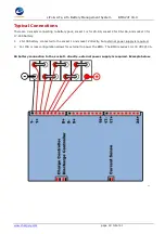
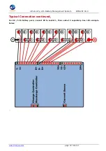
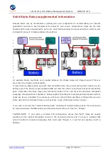
Delay Board Implementation Examples:
Shown with BMS8T, the configuration is the same between BMS8T, BMS16T & BMS24T
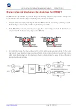
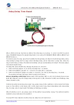
The Small Relay in this example is a simple automotive "Make & Break relay".
The simplest and most
common form of relay. The circuit between terminals 30 and 87 is Closed "on" when energized and Open "off"
when de-energized, this is known as NO (Normally Open). Terminals 85 and 86 actuate the relay. Suggested
to use a 12VDC / 10A or greater relay.
In this configuration, both the Charge and Discharge relays must be of equal Amperage rating as they share
the common lines between the Motor / Inverter and battery.
For example: 24V/4000W Inverter will draw (4000W ÷ 24VDC = 166.66A) X 1.25 = 208.3A
Note a Low Frequency Inverter is capable of 3X the wattage (12,000W) for momentary surge.
The relays in this case should be sized 200A or greater


