25
COMPONENT REPLACEMENT
COMPONENT REPLACEMENT
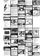
Pressure Reducing Valve (PRV) Adjustment
1. Turn the main water supply to machine off.
2. Flip the power toggle switch to OFF.
3. Turn off main incoming power.
4. Loosen the locknut on the adjusting screw in the top of the PRV.
5. Turn the adjusting screw clockwise to increase the flowing pressure to the machine.
6. Turn the adjusting screw counterclockwise to reduce the flowing pressure to the machine.
7. Observe the pressure reading on the control panel to confirm the proper setting of
20-22 psi/138-151 kPa during the final rinse.
8. Tighten the locknut on the adjusting screw.
9. If the proper pressure cannont be acheived then check the water pressure before the PRV, it
may be too low, or replace the PRV.
Vacuum Breaker
The vacuum breaker is located at the top right rear corner of the unit. It prevents siphoning of
water from the unit back in into the potable water supply. The vacuum breaker contains a
replaceable float assembly.
CAUTION:
Use extreme caution when servicing the breaker to prevent damage to the final rinse
manifold.
1. Turn the main water supply to the machine off.
2. Flip the power toggle switch to OFF.
3. Turn off main incoming power.
4. Remove the retaining screw in the vacuum breaker cap. Remove cap.
5. Remove the vacuum breaker top with a wrench turning
counterclockwise.
6. Remove the float assembly with a pair of needle nose pliers.
7. Inspect the bore of the vacuum breaker. If pitted, replace the entire
vacuum breaker. Otherwise, install the repair kit.
8. Reassemble in the reverse order.
9. Restore the power and water, and check for proper operation.
!
Figure 10
Vacuum Breaker
Содержание PP-28 Corner
Страница 4: ...REVISION RECORD CONT REVISIONS ii ...
Страница 43: ...35 REPLACEMENT PARTS REPLACEMENT PARTS ...
Страница 44: ...36 REPLACEMENT PARTS 5 2 5 1 5 4 3 5 5 5 6 9 7 10 11 12 A B A A 8 Figure 22 Panels ...
Страница 48: ...40 REPLACEMENT PARTS 2 1 1 3 6 7 3 5 4 A A A 8 9 10 B B B Figure 24 Cable Pulley Assembly ...
Страница 50: ...42 REPLACEMENT PARTS 2 3 3 4 8 7 6 5 3 5 5 5 3 9 10 1 11 12 Figure 25 Counterweight System ...
Страница 64: ...56 REPLACEMENT PARTS 2 3 6 4 5 1 7 Figure 32 Scrap Screens Baskets ...
Страница 75: ...67 REPLACEMENT PARTS THIS PAGE INTENTIONALLY LEFT BLANK ...
Страница 83: ...75 REPLACEMENT PARTS THIS PAGE INTENTIONALLY LEFT BLANK ...
Страница 84: ...76 REPLACEMENT PARTS 3 5 6 4 5 5 5 1 2 5 3 Figure 40 Side Mount Booster Cabinet ...
Страница 86: ...78 REPLACEMENT PARTS 1 2 3 4 7 8 6 9 10 4 11 12 13 5 Figure 41 Pump Assembly ...
Страница 88: ...80 REPLACEMENT PARTS 3 4 5 6 7 8 10 1 2 9 11 11 Figure 42 Machine Control Panel ...
Страница 92: ...84 REPLACEMENT PARTS 7 7 3 6 5 9 1 2 4 8 Figure 44 Booster Control Cabinet Single Tank Canister Shown ...
Страница 94: ...86 REPLACEMENT PARTS 0 1 2 1 2 3 4 6 7 8 5 Figure 45 Vent Fan Control Cabinet Optional ...
Страница 96: ...88 REPLACEMENT PARTS 1 2 3 4 5 Utensils loose items Large Pots Pans Baking sheets Baking Pans Figure 46 Racks ...
Страница 98: ...90 THIS PAGE INTENTIONALLY LEFT BLANK ...
Страница 99: ...91 ELECTRICAL SCHEMATICS ELECTRICAL SCHEMATICS ...
Страница 103: ...98 ...
Страница 104: ...99 ...
Страница 105: ......


