background image

100722 - 3500 Lb. (1588 kg) WiNch

ASSEMbLY

9

ASSEMbLY

Mounting the Winch

This CPE 3,500 lb (1,588 kg) winch is designed with a bolt 
pattern that is standard in this class of winch. Many winch 
mounting kits are available that utilize this bolt pattern for 
the most popular trucks, SUV’s and ATV’s. If you cannot 
find a kit locally, contact CPE and we will provide you with 
the name of a dealer.

 

cAUTiON

See Parts Included Assembly Parts section for torque 
ratings. Mounting bolts must be SAE grade 5 or better 
and torque to 34 ft. lbs (46 N.m).

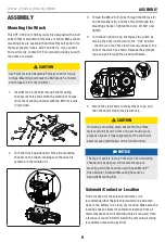
1.  Insert M10×25 (B) bolts through the mounting 

channel (A) holes and attach the aluminum hawse 
(D) to the mounting channel with the M10 lock nuts 
(C) provided.

B

E

F

G

C

D

A

2.  Turn the winch upside down. Place the mounting 

channel on the winch, making sure the winch is 
centered in the middle of it.

3.  Thread the M8×25 (E) bolts through the Ø8 lock (F) 

and flat washers (G), and then thread through the 
mounting channel. Tighten the bolts. DO NOT over 
tighten.

4.  Turn winch right side up. Disengage the clutch by 

moving the Cam Clutch Gear to the “Out” position 
- the arrow on the Cam Clutch Gear would be to the 
back of the winch as shown. Release the synthetic 
rope and pull through the aluminum hawse.

Out

5.  Attach the clevis hook to the synthetic rope, and 

then the hand strap to the clevis hook.

 

cAUTiON

If utilizing a mounting plate, ensure that the three 
major sections (motor, drum and gear housing) are 
properly aligned. Proper alignment of the winch will 
allow for even distribution of the full rated load.

 

NOTicE

The type of vehicle to which the winch and mounting 
channel will be applied, will dictate the type of 
mounting kit that should be used (Speed Mount™ 
Hitch Adapter, Standard Mounting Channel, or 
Specialty Mounting Kit).

Solenoid/contactor Location

Find a location for the solenoid/contactor. It is 
recommended that the solenoid/contactor be mounted 
close to the battery in a clean, dry location. Make sure the 
location chosen allows for sufficient clearance from all 
metal components. Drill mounting holes if required. Once 
a location is found, DO NOT install the unit until all wiring 
is completed (see wiring section).

Содержание 100722

Страница 1: ...important safety precautions which should be read and understood before operating the product Failure to do so could result in serious injury This manual should remain with the product Specifications...

Страница 2: ...Mounting the Winch 9 Solenoid Contactor Location 9 Install the Rocker Switch 10 Wiring the Winch 10 Wiring Diagram 12 Switch Wiring Diagram 12 Operation 13 General Tips for Safe Operation 13 Self Rec...

Страница 3: ...ercise common sense and always err on the side of caution when operating the product to ensure no accident property damage or injury occurs We want you to continue to use and be satisfied with your CP...

Страница 4: ...e control and battery leads when not in use WARNING Avoid shock loads by using the control switch intermittently to take up the slack in the cable rope Shock loads can exceed the rated capacity of the...

Страница 5: ...to the winch Electric winches are designed and made for intermittent use and should not be used in constant duty applications Operation Symbols Some of the following symbols may be used on this produ...

Страница 6: ...rum from the gear train free spool Engaging the clutch In locks the winch into the gear system 6 Mounting Channel 7 Circuit Breaker The circuit breaker is installed as close to the battery as possible...

Страница 7: ...e the synthetic rope onto the drum and minimizes damage to the synthetic rope from abrasion on the winch mount or bumper 12 Winch Connection Cables Used to connect the contactor to the winch motor 13...

Страница 8: ...16 17 1 Lock Nut M10 2 1x 16mm wrench or socket Mini Rocker Switch 1 Hexagon Socket Head Screw M5 x 18 1 1x 4mm allen wrench 2 2 3 3 4 Hexagon Socket Head Screw M5 x 25 2 1x 4mm allen wrench 2 2 3 3...

Страница 9: ...ighten 4 Turn winch right side up Disengage the clutch by moving the Cam Clutch Gear to the Out position the arrow on the Cam Clutch Gear would be to the back of the winch as shown Release the synthet...

Страница 10: ...e in place of the red and black 1 See the Wiring Diagram on the following page for these following steps Connect the yellow and blue cables to the motor terminals on the winch Yellow to the positive t...

Страница 11: ...me cable from the drum and then turn the clutch knob to the In position to engage the gears Press the cable out button on the rocker switch If the drum is turning and releasing more cable then your co...

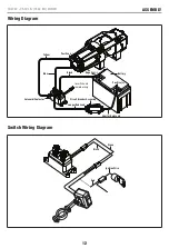
Страница 12: ...mbly 12 Wiring Diagram Blue to switch and remote wiring Yellow Black Longer Red Lead Positive Positive Negative Switch Wiring Diagram Black Green Red Ignition Wire Solenoid Contactor Battery Circuit B...

Страница 13: ...with the exact specifications Inspect the winch installation and bolts to ensure that all bolts are tight before each operation Store the remote control inside your vehicle in a place that it will not...

Страница 14: ...tep over the synthetic rope L Double check your anchors and make sure all connections are secure M Inspect the synthetic rope Make sure there are at least 5 wraps of synthetic rope around the winch dr...

Страница 15: ...inch having been Lubricated using high temperature lithium grease at the factory No internal lubrication is required Lubricate Cable Assembly periodically using a light penetrating oil Synthetic Rope...

Страница 16: ...0 2000 2500 3500 KG 0 454 907 1134 1588 Line Speed 12V DC FPM 12 1 10 8 8 2 7 5 4 9 MPM 3 7 3 3 2 5 2 3 1 5 Motor Current 12V DC A 28 60 90 105 130 Running Time Minutes 5 5 5 5 5 Cooling Time Minutes...

Страница 17: ...able drum does not turn Clutch not engaged Move Clutch to the In position If problem persists a qualified technician needs to check and repair Motor runs slowly or without normal power Insufficient cu...

Страница 18: ...product is deemed to have been misused neglected involved in an accident abused loaded beyond the product s limits modified installed improperly or connected incorrectly to any electrical component N...

Отзывы: