background image

GB-1

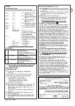
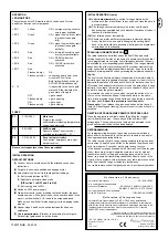
Contents: General Information on
Installation and Use:
Details of Contents:  

Page 1

Before You Begin:

Page 2

Check List:  

Page 2, figs.      - 

Overview of Installation:

Page 2

Installation of Rack Bar:

Page 2, fig. 

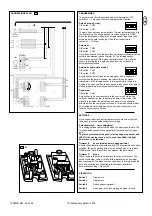
Electrical Installation:

figs.       -      

Installation of Base Plate:

Page 2

Mounting Drive on Base Plate:

Page 2, figs.       

+

-

A

Drive Release Mechanism:  

Page 2, fig. 

Limit Switches:  

Page 2, fig. 

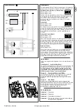
Light Barrier: 

Page 3, figs.       

A

Flashing Lamp:

Page 3, figs.      -      

External Antenna:  

Page 3

Initial Operation:  

Page 3

Maintenance Work:  

Page 3, figs.  

Typical System Set-up:  

Page 4, fig. 

Teaching in Remote Control: 

Page 5, fig.  

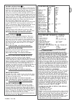
Technical Data:  

Page 3

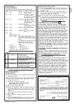
CE Conformity Certificate:  

Page 4

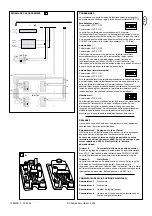
Contents in HC100/HC500 packs

(1)

Drive motor (1x)

(2)

Capacitor (pre-installed) (1x)

(3)

Limit switch A or (1) (1x)

(4) 

Limit switch B or (2) (1x)

(5)

Base plate for drive motor (1x)

(6)

Accessories bag

(7)

Control unit with pre-installed radio receiver(1x)

(8)

Flashing lamp 100287

(9)

Light barrier (pair) 263EML

(10)

Remote control 84333EML

Optional Accessories
(11)

Remote control 84335EML

(12)

Remote control 84330EML

(13)

External Antenna ANT4X-EML

(14)

Key switch 41EML

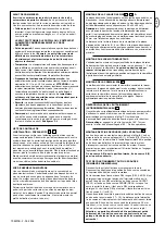
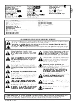
READ THESE IMPORTANT SAFETY INSTRUCTIONS BEFORE STARTING WORK

CAUTION! Only use the drive if you have a clear view of
the gate, if there are no obstacles in the gate's path and
the drive is correctly adjusted. Children should not be
playing near the gate when the drive is to be used.

Disconnect the gate drive from the power supply before
any repairs are made. 

This symbol means 'Caution!'; it is a sign that compliance with the given instruction is required as non-compliance can lead to
persons being injured and property damaged. Please read such warnings carefully.

This gate drive has been designed in such a way and tested to ensure that it offers adequate safety providing its installation
and use exactly comply with the following safety instructions.

Non-compliance with the following safety instructions can lead to persons being seriously injured or property badly damaged.

The sliding gate drive can be activated via push-buttons, key-operated switches, keyless switches (radio) or remote control; once the
drive has been disengaged with the appropriate key, the gate can be opened by hand. The sequence of functions initiated by a
command issued via a remote control, push-button, etc. depends on how the control's electronic system has been set. 

Electric cables should be laid in accordance with local
building and installation regulations and may only be
connected to a properly earthed mains supply by a
qualified electrician. 

When installing the drive, sufficient clearance must be left
between the item driven and the surrounding parts of the given
building (e.g. a wall) due to the opening movement of the item
driven. 

Automatically controlled equipment must be
disconnected from the mains when maintenance work
e.g. cleaning is being performed. 
In the case of a permanently laid installation, an
isolating device must be fitted to ensure that all the
connections can be isolated via a switch (min. 3mm
contact opening clearance) or a separate fuse.

Take great care when working with tools and
hardware. Never wear rings, watches or loose clothing
when you are performing installation or repair work on
the gate. 

Make sure that the persons installing, servicing or using
the drive observe these instructions. 

Keep the

instructions in a safe yet readily accessible place.

Please remove all locks fitted to the gate in order to avoid
damaging the gate. 

It is important to keep the gate in good working order.
Gates that do not open and close smoothly and fully
should be repaired without delay. Do not try to repair
the gate yourself. Have it done by a person qualified.

Keep any extra items of equipment and accessories out of
the reach of children. Do not allow children to operate the
push-buttons or remote control. Serious injuries can be
caused by a gate that is closing. 

Once installation has been completed, you must check
that the mechanism is correctly adjusted and that the
drive, safety system and emergency release all
function as they should. 

Once the drive has been installed, the gate must be
tested to ensure that there is no risk of persons trapping
or cutting themselves. 

If the gate system is fitted with a slip-gate, the drive
may not be started or move further until the slip-gate
has been closed properly. 

1

4

5

7

8

9

10

11

12

2

3

6

6

13

A

C

709207B-GB - 05.2004

Содержание MotorLift HC100

Страница 1: ...HC100ML 2 HC500ML 2 F r Service 43 2623 72225 33 Voor Service 31 0 20 684 7978 A NL F r Service 49 0 6838 907 100 Pour Service 33 0 3 87 95 39 28 For Service 0800 317847 D F GB 0678 709207B Mai 04...

Страница 2: ...ktionsablauf nach Bet tigung der Befehlgeber Fernbedienung Taster etc h ngt von der Einstellung in der Steuerelektronik ab Elektrische Leitungen sind entsprechend den lokalen Bau und Elektroinstallati...

Страница 3: ...eit ge ffnet und nicht geschlossen Achtung Ein Schiebetor mu zwangsgef hrt sein d h es darf nicht m glich sein da das Tor aus der F hrung f hrt Ein Endanschlag in beiden Richtungen mu vorhanden sein B...

Страница 4: ...e in regelm igen Abst nden monatlich den festen Sitz der Beschl ge des Tores und des Antriebs Entrieglen Sie den Antrieb und testen Sie die Funktion des Tores Nur ein leichtg ngiges Tor wird auch gut...

Страница 5: ...gramm Schalter DIPP Schalter 18 TEST Test Taster ffnet komplett 2 1 2 3 4 5 6 7 8 9 10 11 12 13 14 15 16 17 ANSCHL SSE M1 230Volt 1 L L 230V 50Hz 10 2 Erdung Versorgung der Steuerung Antrieb Zubeh r 3...

Страница 6: ...code Damit kann Ihr Schiebetortorantrieb nur mit einem entsprechend gleich codierten Handsender aktiviert werden Die Reichweite ist von rtlichen Bedingungen abh ngig Das Empf ngerteil der Motorsteueru...

Страница 7: ...Tor zu betreiben muss mit dem Schl sselschalter oder Handsender kontinuierlich Signal zur Steuerung gegeben werden Wird das Signal unterbrochen bleibt das Tor stehen und wechselt die Fahrtrichtung bei...

Страница 8: ...rrespondante le portail peut tre ouvert la main La s quence de fonctions apr s actionnement de l impulseur t l commande touche etc d pend du r glage de l lectronique de commande Les c bles lectriques...

Страница 9: ...de se fermer apr s coulement du temps de pause r gl Attention un portail coulissant doit tre parfaitement guid Autrement dit il ne doit en aucun cas pouvoir sortir de son guidage Une but e de fin de...

Страница 10: ...ntra nement n est pas la panac e pour rem dier au fonctionnement d fectueux d un portail La s curit d un portail coulissant peut galement tre assur e par des cl tures des murs etc Voir fig 12 CARACTER...

Страница 11: ...1 Commutateur de programme commutateur DIP 18 TEST Touche de test ouverture compl te 2 RACCORDEMENTS M1 230Volt 1 L L 230V 50Hz 10 2 Mise la terre Alimentation de la commande de l entra nement des acc...

Страница 12: ...s fonctionne avec un code de s curit priv pr programm par ordinateur Votre ouvre portail ne peut donc tre activ que par une t l commande pr sentant le m me code La port e d pend des conditions locales...

Страница 13: ...e Automatique Homme mort Commutateur DIP 4 ON Pour fonctionner la commande du portail doit recevoir un signal continu provenant de l interrupteur cl ou de la t l commande En cas d interruption du sign...

Страница 14: ...e the drive has been disengaged with the appropriate key the gate can be opened by hand The sequence of functions initiated by a command issued via a remote control push button etc depends on how the...

Страница 15: ...not close after the set pause when in programme selection automatic mode Caution A sliding gate must run in a guide rail and should not be able to leave the rail This means end stops need to be fitte...

Страница 16: ...rive are all firmly in place Disengage the drive and check gate functionality Only an easy running gate will work well with a drive A drive is no substitute for a poorly functioning gate A sliding gat...

Страница 17: ...ded 17 SW1 Programme switch DIP switch 18 TEST Test push button opens fully 2 CONNECTIONS M1 230Volt 1 L L 230V 50Hz 10 2 Earthing Power supply to control unit drive accessories 3 N zero conductor 230...

Страница 18: ...ed handset The range obtained depends on the given local environment The receiver element of the motor control has an integrated self learn function It can be set to the handset s pre programmed code...

Страница 19: ...matic mode Dead man DIP switch 4 ON A signal has to be sent constantly to the control unit via the key switch or handset in order to operate the gate in this mode If the signal is interrupted the gate...

Страница 20: ...rde apparaten moeten van de stroomtoevoer worden afgesloten wanneer er onderhoudswerkzaamheden bijvoorbeeld reiniging worden uitgevoerd In de uiteindelijke configuratie van de installatie is een schei...

Страница 21: ...et ingestelde pauze interval geopend en niet gesloten NB Een schuifhek moet coulissegeleiding hebben d w z het mag niet mogelijk zijn dat het hek uit de geleiding beweegt Er moet in beide richtingen e...

Страница 22: ...g en test of het hek soepel beweegt Alleen een hek dat licht loopt zal ook goed met een aandrijving functioneren Het stroef bewegen van het hek wordt niet gecompenseerd door het gebruik van een aandri...

Страница 23: ...ar DIP schakelaar 18 TEST Test knop opent volledig 2 AANSLUITINGEN M1 230Volt 1 L L 230V 50Hz 10 2 Aardverbinding Voorziening voor de besturingseenheid aandrijving toebehoren 3 N nulleider 230Volt 4 L...

Страница 24: ...ke omstandigheden Het ontvanggedeelte van de motorbesturing heeft een ge ntegreerde zelfleerfunctie Deze kan op de voorgeprogrammeerde code van de handzender worden ingesteld door te drukken op de pro...

Страница 25: ...laar 4 ON Om het hek in werking te stellen moet er met sleutelschakelaar of handzender een permanent signaal aan de besturingseenheid worden gegeven Zodra het signaal wordt onderbroken blijft het hek...

Страница 26: ...HC100ML 2 HC500ML 2 F r Service 43 2623 72225 33 Voor Service 31 0 20 684 7978 A NL F r Service 49 0 6838 907 100 Pour Service 33 0 3 87 95 39 28 For Service 0800 317847 D F GB 0678 709276 Mai 04...

Страница 27: ...1 200 215 12 40 60 28 30 1 2 160 mm 100 m m 180 mm M10x50 270 mm 75 mm 4 5 6 6 A 7 709276 05 2004 1...

Страница 28: ...2 A 1 B 2 2 3 0 V 50 Hz 9 7 6 5 8 2 1 3 4 0 8 10 11 12 13 N L 2 1 Logic Board 2 1 709276 05 2004 2...

Страница 29: ...3 709276 05 2004 Chamberlain GmbH 2004 1 2 14 15...

Отзывы: