background image

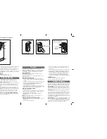
To Open the Door Manually

The door should be fully
closed if possible. Pull down
on the emergency release
handle and lift the door
manually. To reconnect the
door to the opener, press the
door control push bar.

The 

lockout feature

prevents

the trolley from reconnecting
automatically. Pull the
emergency release handle
down and back (toward the
opener). The door can then
be raised and lowered
manually as often as
necessary. To disengage the
lockout feature, pull the
handle straight down. The
trolley will reconnect on the
next UP or DOWN operation,
either manually or by using
the door control or remote.

To prevent possible SERIOUS INJURY or DEATH from a
falling garage door:

• If possible, use emergency release handle to

disengage trolley ONLY when garage door is CLOSED.
Weak or broken springs or unbalanced door could
result in an open door falling rapidly and/or
unexpectedly.

• NEVER use emergency release handle unless garage

doorway is clear of persons and obstructions.

• NEVER use handle to pull door open or closed. If

rope knot becomes untied, you could fall.

27

Trolley
Release 
Arm

NOTIC

E

Emergency
Release 
Handle
(Pull Down)

Trolley
Release 
Arm

NOTICE

Emergency
Release Handle
(Down and Back)

WARNING

CAUTION

WARNING

WARNING

LOCKOUT POSITION

MANUAL DISCONNECT

POSITION

Using the Wall-Mounted 
Door Control

THE MOTION DETECTING DOOR 
CONTROL

Press the push bar to open or
close the door. Press again to
reverse the door during the
closing cycle or to stop the door
while it's opening.

This door control contains a
motion detector that will
automatically turn on the light
when it detects a person entering
the garage. This feature can be easily turned off for
extended work light use.

Light feature

Press the Light button to turn the opener light on or
off. It will not control the opener lights when the door
is in motion. If you turn it on and then activate the
opener, the light will remain on for 4-1/2 minutes.
Press again to turn it off sooner. The 4-1/2 minute
interval can be changed to 1-1/2, 2-1/2, or 3-1/2
minutes as follows: Press and hold the Lock button
until the light blinks (about 10 seconds). A single blink
indicates that the timer is reset to 1-1/2 minutes.
Repeat the procedure and the light will blink twice,
resetting the timer to 2-1/2 minutes. Repeat again for
a 3-1/2 minute interval, etc., up to a maximum of four
blinks and 4-1/2 minutes.

When using the opener lights as working lights, we
recommend that you first disable the motion sensor
See 

Automatic Light Feature, 

following.

Automatic Light Feature: 

The opener light will

turn on automatically when a person enters the
garage. When a person walks in front of the door
control, the light will come on for five minutes, then
shut off. This feature works by detecting body heat
and may not work in temperatures around 100˚F
(37.7˚C).

To disable this feature, slide the Detector Switch on
the right side of the door control down (off).

We recommend that you disable the motion sensor
when using the opener lights as working lights.
Otherwise, they will turn off automatically if you are
working beyond the sensor’s range. 

Lock feature

Designed to prevent operation of the door from hand-
held remote controls. However, the door will open
and close from the Door Control, the Outside Keylock
and the Keyless Entry Accessories.

To activate, press and hold the Lock button for 2
seconds. The push bar light will flash as long as the
Lock feature is on.

To turn off, press and hold the Lock button again for
2 seconds.The push bar light will stop flashing. The
Lock feature will also turn off whenever the “Learn”
button on the motor unit panel is activated.

LOCK

LIGHT

Push
Bar

Lock 
Button

Light
Button

Detector 
Switch

Additional feature when used with the
3-Button hand-held remote

To control the opener lights:

In addition to operating the door, you
may program the remote to operate the
lights.

1. With the door closed, press and hold a small

remote button that you want to control the light.

2. Press and hold the Light button on the door

control.

3. While holding the Light button, press and hold the

Lock button on the door control.

4. After the opener lights flash, release all buttons.

Содержание LiftMaster 3575

Страница 1: ...Only Owner s Manual Please read this manual and the enclosed safety materials carefully Fasten the manual near the garage door after installation The door WILL NOT CLOSE unless the Protector System is...

Страница 2: ...c chart 30 Programming 31 32 To add or reprogram a hand held remote control 31 To erase all codes 31 3 Button remotes 31 To add reprogram or change a Keyless Entry PIN 32 Repair Parts 33 34 Rail assem...

Страница 3: ...your garage door Before you begin Disable locks Remove any ropes connected to garage door Complete the following test to make sure your garage door is balanced and is not sticking or binding 1 Lift t...

Страница 4: ...on of your opener Access Door Safety Reversing Sensor Safety Reversing Sensor Slack in chain tension is normal when garage door is closed Gap between floor and bottom of door must not exceed 1 4 6 mm...

Страница 5: ...Button Remote Control 2 Safety Reversing Sensors 1 Sending Eye and 1 Receiving Eye with 2 Conductor White White Black Bell Wire attached Safety Sensor Bracket 2 One Piece rail Styrofoam Chain Pulley B...

Страница 6: ...o the opener Cut tape from T rail chain and styrofoam REMOVE STYROFOAM ASSEMBLY STEP 2 Attach the Chain Spreader Attach chain spreader to the motor unit with two screws Position chain over chain sprea...

Страница 7: ...uce the risk of SEVERE INJURY or DEATH WARNING WARNING WARNING 1 READ AND FOLLOW ALL INSTALLATION WARNINGS AND INSTRUCTIONS 2 Install garage door opener only on properly balanced and lubricated garage...

Страница 8: ...the door NOTE If the total number of inches exceeds the height available in your garage use the maximum height possible or refer to page 9 for ceiling installation To prevent possible SERIOUS INJURY...

Страница 9: ...age Door Header Wall Garage Door UP CEILING MOUNT ONLY Wall Mounting Holes Optional Wall Mounting Holes The nail hole is for positioning only You must use lag screws to mount the header bracket UP CEI...

Страница 10: ...u ll need help Have someone hold the opener securely on a temporary support to allow the rail to clear the spring Position the rail bracket against the header bracket Align the bracket holes and join...

Страница 11: ...g an ideal door to rail distance Remove foam packaging Raise the opener onto a stepladder You will need help at this point if the ladder is not tall enough Open the door all the way and place a 2x4 la...

Страница 12: ...the motor unit to the structural support 2 Cut both pieces of the hanging bracket to required lengths 3 Drill 3 16 pilot holes in the structural supports 4 Attach one end of each bracket to a support...

Страница 13: ...t terminals as follows white to white and white red to red NOTE When connecting multiple door controls to the opener twist same color wires together Insert wires into quick connect holes white to whit...

Страница 14: ...e hole in the release arm of the outer trolley Adjust rope length so the handle is 6 feet 1 83 m above the floor Ensure that the rope and handle clear the tops of all vehicles to avoid entanglement Se...

Страница 15: ...he black line wire to the screw on the brass terminal the white neutral wire to the screw on the silver terminal and the ground wire to the green ground screw The opener must be grounded Reinstall the...

Страница 16: ...r Either can be installed on the left or right of the door as long as the sun never shines directly into the receiving eye lens The mounting brackets are designed to clip onto the track of sectional g...

Страница 17: ...p hugging the back edge of the track as shown in Figure 1 If your door track will not support the bracket securely wall installation is recommended Wall installation Figure 2 3 Place the bracket again...

Страница 18: ...ng eyes will glow steadily if wiring connections and alignment are correct The sending eye amber indicator light will glow regardless of alignment or obstruction If the green indicator light in the re...

Страница 19: ...ollows depending on your door s construction Metal or light weight doors using a vertical angle iron brace between the door panel support and the door bracket Drill 3 16 fastening holes Secure the doo...

Страница 20: ...INUM STEEL DOORS WITH GLASS PANEL ETC NOT PROVIDED ONE PIECE DOORS Please read and comply with the warnings and reinforcement instructions on the previous page They apply to one piece doors also Cente...

Страница 21: ...re 3 Hole alignment alternative If holes in curved arm are above holes in straight arm disconnect straight arm Cut about 6 15 cm from the solid end Reconnect to trolley with cut end down as shown Brin...

Страница 22: ...hers 5 16 Ring Fastener Straight Arm Bolts 5 16 18x7 8 Door Bracket Clevis Pin 5 16 x1 1 4 Curved Door Arm Press the Door Control push button The trolley will travel to the fully closed position Manua...

Страница 23: ...nutes and try again NOTE If anything interferes with the door s upward travel it will stop If anything interferes with the door s downward travel including binding or unbalanced doors it will reverse...

Страница 24: ...small adjustments until the door completes a close cycle After each adjustment run the opener through a complete travel cycle Do not increase the force beyond the minimum amount required to close the...

Страница 25: ...un the opener through 3 or 4 complete travel cycles to test adjustment If the unit continues to fail the Safety Reverse Test call for a trained door systems technician IMPORTANT SAFETY CHECK Test the...

Страница 26: ...s maximum Security light feature Lights will also turn on when someone walks through the open garage door With a Motion Detecting Door Control this feature may be turned off as follows With the opener...

Страница 27: ...can be changed to 1 1 2 2 1 2 or 3 1 2 minutes as follows Press and hold the Lock button until the light blinks about 10 seconds A single blink indicates that the timer is reset to 1 1 2 minutes Repea...

Страница 28: ...ved including interference that may cause undesired operation MAINTENANCE SCHEDULE Once a Month Manually operate door If it is unbalanced or binding call a trained door systems technician Check to be...

Страница 29: ...nts to force or travel limits The need for occasional adjustment for the force and limit settings is normal Weather conditions in particular can affect door travel Refer to Adjustment Step 1 Adjust th...

Страница 30: ...ntrol touch wires together If motor unit activates replace door control If motor unit does not activate disconnect door control wires from motor unit Momentarily short across red and white terminals w...

Страница 31: ...e heard 1 Press and release the learn button on the motor unit The learn indicator light will glow steadily for 30 seconds 2 Within 30 seconds press and hold the button on the hand held remote that yo...

Страница 32: ...he four buttons for the present PIN then press and hold the button The opener light will blink twice Release the button 2 Press the new 4 digit PIN you have chosen then press Enter The motor unit ligh...

Страница 33: ...M 3 button remote 3 10A20 3V2032 Lithium battery 4 29B137 Remote control visor clip 5 41A2828 Emergency Release rope handle assy 6 41B4494 1 2 Conductor bell wire white white red 7 41A5047 1 Door brac...

Страница 34: ...0 Capacitor 56uF 8B 30B529 Capacitor 40uF 8C 41A5637 Resistor 9 41A3150 Terminal block w screws 10 41D5563 1 Universal replacement motor bracket assembly Complete with Motor worm bracket gear case bea...

Страница 35: ...itors or service persons This temporary password can be limited to a programmable number of hours or entries 78LM 3 Button Mini Remote Control with Security With key ring and fastening strip 902LM 903...

Страница 36: ...turned to Seller for warranty repair which upon receipt by Seller are confirmed to be defective and covered by this limited warranty will be repaired or replaced at Seller s sole option at no cost to...

Отзывы: