


10
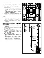
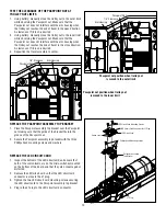
TEST THE CLEARANCE OF THE PASSPOINT NUT AT
TROLLEY NUT LIMITS
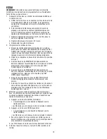
1. Using battery, manually move the trolley nut to the outer limit
while observing the Passpoint nut. Make sure that the
Passpoint nut does not interfere with the arm housing when
the trolley nut reaches the end of travel in the open direction.
A clearance of 1/8 inch is desired.
2. Using battery, manually move the trolley nut to the inner limit
while observing the Passpoint nut. Make sure that the
Passpoint nut does not interfere with the arm housing when
the trolley nut reaches the end of travel in the close direction.
A clearance of 1/8 inch is desired.
3. Reposition the travel assembly to center.
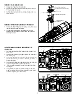
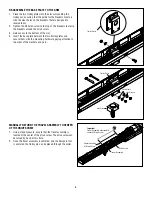
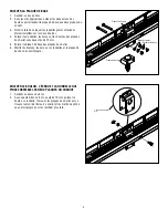
REPLACE THE PASSPOINT ASSEMBLY TOP BRACKET
1. Place the Passpoint assembly top bracket over the Passpoint
nut making sure that the guide of the bracket fits into the
groove of the Passpoint nut.
2. Secure the Passpoint assembly top bracket with the three
Phillips head mounting screws and washers.
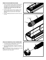
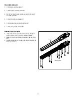
REPLACE THE LED CIRCUIT CARD
1. Inspect the bottom of the LED circuit card and ensure that
both of the switch levers are on the micro-switches mounted
on the bottom of the board, and that they are not damaged or
distorted.
2. Replace the LED circuit card so that the LED circuit card
connector is close to the J1 plug.
3. Tighten the two LED circuit card mounting screws securing
the LED circuit card to the Passpoint assembly top bracket.
4. Plug in the J1 plug to the LED circuit card connector.
Passpoint Nut
Arm Housing
1/8” Clearance
Passpoint Nut
Arm Housing
1/8” Clearance
Passpoint nut position when trolley nut
is moved to the outer limit
Passpoint nut position when trolley nut
is moved to the inner limit
LED Circuit Card
Passpoint Assembly
Top Bracket
LED Circuit Card Mounting Screws
3 Phillips Head Mounting Screws
J1 Plug
LED Circuit Card Connector for J1 Plug
Switch Levers


