Base Unit
2019 Cervis, Inc.
7
1.4
External Protection Devices for Relay Contacts
Depending on the model, the BU-xH6R may have internal snubbing circuits to protect the relay
contacts. (See Table 4, AC Sup.) Each snubber consists of a 47
Ω resistor in series with a 0.1 µF
capacitor across each relay contact. However, the internal snubbers may not be adequate for all
loads and applications. An MOV
—or Metal Oxide Varistor—is a protection device used to
suppress high-transient voltages that can cause relay contact deterioration, especially when
switching inductive loads such as solenoids or relay coils. They protect circuits against
excessive transient voltages by clamping the voltage to a safe level and dissipating the
unwanted energy. To provide proper protection, the MOV must have a voltage rating and an
energy dissipation rating appropriate to the application. Other devices
—such as power Zener
diodes or R-C snubbers
—may be necessary, depending on the application and whether the
switched circuits are AC or DC.
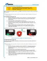
When using contactors or solenoids with SmaRT systems, Cervis, Inc. advises using external
protective devices by connecting them across the coils as shown in the examples below using
MOVs.
Figure 7. Typical MOV and Suggested MOV Wiring Across the Contactor Coils
In some applications, internal snubbers may not be desired. (See Table 4, AC Sup.) The
–NOS
option can be specified to omit them. However, this can leave the contacts vulnerable to
switching transients and arcing. Contact Cervis, Inc. Customer Service for assistance in
choosing appropriate contact protection.
1.5
Standard Configuration
Output Check/Operating Mode Interlock
In the default output configuration, there is an interlock that prevents an output from activating if
an adjacent handheld button is pressed at the same time as the intended button. Once the
remote is associated to the base unit (see Appendix C), outputs
—when properly wired—respond
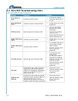
and are indicated by the base unit OUT (output) LED as listed in Table 2.
Table 2. Base Unit Output LED Interlock Indications
Handheld Remote
Momentary Action
Command
BU-xH6R Result
Press and hold function
corresponding to Output 1
Activate Output K1
Output K1 active; Output LED lights and remains lit
until the PTO Output 1 is released.
Press and hold function
corresponding Output 2
Activate Output K2
Output K2 active; Output LED lights and remains lit
until the PTO Output 2 is released.
Press and hold function
corresponding Output 1 and
Output 2
Operating Mode Interlock
Operating Mode Interlock prevents K1 and K2 output
activity. Output LED is unlit.
Press and hold function
corresponding Output 3
Activate Output K3
Output K3 active; Output LED lights and remains lit
until the PTO Output 3 is released.
Press and hold function
corresponding Output 4
Activate Output K4
Output K4 active; Output LED lights and remains lit
until the PTO Output 4 is released.


