5
1.3 CLEARANCES
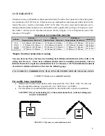
Clearances to any combustibles when measured directly from the floor protector to the ceiling must
be a minimum of 84" (2134 mm). Clearances to any combustibles when measured directly from the
front of the stove must be a minimum of 48" (1219 mm). The stove must also be placed so as to
maintain the minimum clearances to combustible walls specified for each type of connector used.
See Table 1.3 below for all clearance measures. Refer to Figure 1.3 for a diagram of each of the
measures A through C.
Clearances to combustible materials
MODELS
BACK (A)
Single wall pipe / Double wall
SIDES (B)
Single wall pipe / Double wall
CORNERS (C)
Single wall pipe / Double wall
HEIGHT (D)*
S244
15.5" (395mm) / 15.5" (395mm)
18" (455mm) / 18" (455mm)
10" (255mm) / 10" (255mm)
84" (2.13m)
FW2470
17" (430mm) / 5.5" (140mm)
10.5" (265mm) / 2.5 (65mm)
10.5" (265mm) / 2.5 (65mm)
84" (2.13m)
FW2700
15.5" (395mm) / 15.5" (395mm)
17.5" (420mm) / 17.5" (420mm)
11" (280mm) / 11" (280mm)
84" (2.13m)
FW3000
15" (380mm) / 15" (380mm)
26" (660mm) / 26" (660mm)
12" (305mm) / 12" (305mm)
84" (2.13m)
*Height, from floor protection to ceiling
You may decrease these clearances by installing heat radiation shields between the walls or the
ceiling and the stove. These heat radiation shields must be installed permanently, and can
include sheet metal, a rigid non-combustible sheet or a masonry wall. The installation standards
of such heat radiation shields are listed on the following page.
IT IS STRICTLY FORBIDDEN TO PLACE WOOD WITHIN MINIMUM CLEARANCES
TABLE 1.3 Clearances to combustible materials
For mobile home installation
•
Outside air kit with a listed double wall connector(CAN: ULC S641; USA: UL103) and
listed compatible chimney system(CAN: ULC S629; USA: UL103HT)
•
Use clearances from combustibles specified in the double wall connector installation.
CAUTION: The structural integrity of the mobile home floor, wall and ceiling/roof
must be maintained.
...............................................
FIGURE 1.3 Clearances to combustible materials
Содержание FW2470
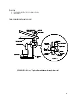
Страница 20: ...19 Typical installation through the ceiling FIGURE 2 2 1 B Typical Installation Through the Ceiling ...
Страница 26: ...25 FIGURE 2 2 2 B Factory Built Thimble ...
Страница 27: ...26 FIGURE 2 2 2 C Brick Thimble ...
Страница 29: ...28 FIGURE 2 3 B Minimum Slope Avoid 90 degree eblows We recommend that you use two 45 degree elbows instead ...
Страница 47: ...46 ...


