9
STEP 9 Attach the Main Rotor Head
STEP 9 Attach the Main Rotor Head
STEP 9 Attach the Main Rotor Head
STEP 9 Attach the Main Rotor Head
STEP 9 Attach the Main Rotor Head
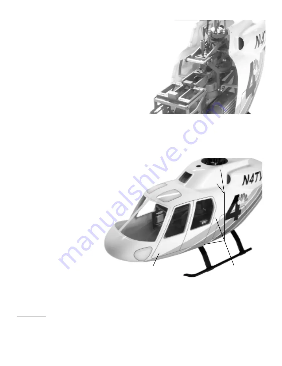
Now the rotor head assembly must be re-attached, insert the main
shaft through the top bearing, the mast stopper and insert the
M3x16 Socket Cap screw below the main gear at a 45° angle.
Once through the auto-hub use a 2.5hex key to turn the bolt
while holding the M3 Locknut with pliers from the other side
at 45° degree angle. Access to the set screws in the mast
stopper is possible through the elevator lever assembly
(disconnect the lever to do this) but remember to pull up
on the main shaft first, tighten one set screw then remove
the second to apply threadlock. Finally, remove the first,
apply threadlock and tighten in place. If using the
slipper unit, access is possible between the starter
shaft and the side frames from the front.
STEP 10 Front Nose
STEP 10 Front Nose
STEP 10 Front Nose
STEP 10 Front Nose
STEP 10 Front Nose
The front nose is attached with four M3x8 Phillips Self Tapping screws from each side. Bonded to the inside are
small 3/8” plywood squares that the hold the screws in place. Take the time now to mount the gyro, receiver and
battery pack (wrapped in foam) inside the front nose if it wasn’t already done for test
flying. The location for the gyro is on the battery tray beside the collective
and throttle servos. Having completed the mechanics, lift the
helicopter by the flybar held perpendicular to the
length of the helicopter and continue to
move the battery pack forward until
balance is achieved. It maybe necessary
to construct an anchor, like a few
simple metal hooks bonded to the
inside of the nose to hold rubber
bands securing the battery pack. If
more weight is necessary, adding
weight is acceptable but be
cautious to the amount, if lead is
being used, bond it as far forward
as possible. See Step 14.
Kit
Kit
Kit
Kit
Kit V
V
V
V
Ver
er
er
er
ersion
sion
sion
sion
sion
Front Body
(unfinished)
[CN1075-1]
M3x8 Self Tapping
Screws x 8
[CN1075-5]
Mark the four screw locations
on the each side of the front
nose with a pencil. Using tape,
attach the front to the rear body and slowly drill each of the eight holes using a 3/32” [2.5mm] drill bit. Remove
the front nose and roughen one side of the eight plywood blocks and the area around the inside hole on the rear
body. Remember that the fiberglass parts are molded using Polyester resin and as a result, “Epoxy” type of glue
will not bond to the fiberglass. Any time two components are bonded to the fiberglass, slow to medium speed CA
(cyanoacrylate) adhesive is necessary. Using slow-CA bond each plywood block in place, clamp until dry. Redrill
each hole in the rear body through the plywood blocks and using one M3x8 Phillips Self Tapping screw, insert
and form the threads. After the fuselage is painted the front nose can be attached, remember to paint the screws to
match the color scheme.
Twinstar Detail Manual
Twinstar Detail Manual
Twinstar Detail Manual
Twinstar Detail Manual
Twinstar Detail Manual


