background image

10

STEP 11  Bottom Hatch

STEP 11  Bottom Hatch

STEP 11  Bottom Hatch

STEP 11  Bottom Hatch

STEP 11  Bottom Hatch

STEP 12  Attaching the Windshields

STEP 12  Attaching the Windshields

STEP 12  Attaching the Windshields

STEP 12  Attaching the Windshields

STEP 12  Attaching the Windshields

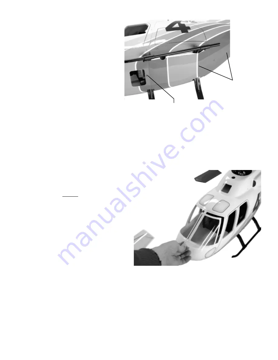
If an exhaust diverter is to be used, install
before the bottom hatch is attached. The
bottom hatch is already cut to fit the landing
gear on the scale mechanics. Start by insert-
ing the rear cutouts and gently flexing the
ears to engage the rear struts, next grasp the
hatch with both hands, fingers on the side
edges and thumbs centered at the front and
gently bend the hatch in a “U” shape to allow
the front lip of the hatch to be inserted under
the edge of the front nose. Secure the hatch
using six M3x8 Phillips Self Tapping Screws.

Rear Body

with Bottom

Hatch

(unfinished)

[CN1075-2]

M3x8 Self

Tapping

Screws x 6

[CN1075-5]

Kit

Kit

Kit

Kit

Kit V

V

V

V

Ver

er

er

er

ersion

sion

sion

sion

sion

Mark the six screw locations on the hatch with a
pencil. Using tape, attach the hatch to the rear body
and slowly drill each of the six holes using a
3/32” [2.5mm] drill bit. Remove the hatch and roughen one side of the six plywood blocks and the area around
the inside hole on the rear body. Using slow-CA bond each plywood block in place, clamp until dry. Redrill each
hole in the rear body through the plywood blocks and using one M3x8 Phillips Self Tapping screw, insert and
form the threads. After the fuselage is painted the hatch can be attached, remember to paint the screws to match the
color scheme.

Twinstar Detail Manual

Twinstar Detail Manual

Twinstar Detail Manual

Twinstar Detail Manual

Twinstar Detail Manual

Apply a thin 1/16” [1.5mm] bead of adhesive centered in the recessed
surface. Pick up the windshield by the edges only, remember  “Goop” or
“Goop Fingerprints” cannot be removed if they touch a clear part.
Using single-use “Hobby grease syringes” are great and really
make this a simple task as the adhesive width and amount
can be easily controlled. Let dry for 24 hours. An
excellent alternative is to use “R/C 56 Canopy
Glue” from any airplane hobbyshop. This adhesive
remains white until fully curred in 24-48 hours
(slow but very good) but can be cleaned up using a
cloth and will not damage or scuff clear parts. When
dry, it is very strong. After bonding, apply “magic”
tape to secure the windshield halves until dry.

STEP 13  Fueling, Glow Plug Extension and Antenna Routing

STEP 13  Fueling, Glow Plug Extension and Antenna Routing

STEP 13  Fueling, Glow Plug Extension and Antenna Routing

STEP 13  Fueling, Glow Plug Extension and Antenna Routing

STEP 13  Fueling, Glow Plug Extension and Antenna Routing
If you have not already considered these items, now is the time. Most scale helicopter present new challenges to
simply change the glow plug when shrouded inside the fuselage. Century makes most items to solve these as
follows: CN2054 Universal Glow Wrench (check for compatibitity), CN2222 Remote Glow Plug Adapter -
absolutely essential for all model helicopters and CNT4444 In-line fueling valve with filter and filler - avoids
pulling the fuel line from the carburator to fuel the helicopter. The antenna wire needs to be routed in a path that
avoids the wire from touching any metal surfaces or servo wires. It is best that all the servo leads be collected and
secured on one side of the mechanics leaving the opposite side for the antenna. Whether you prefer the original
wire or use a “mini-whip” antenna, make sure that anytime the wire needs to cross any metal, use a short 1/2”
[12mm] length of fuel tubing to insulate the wire and attach with a tie wrap. Clean installations always work best.

Содержание Twinstar CN1075

Страница 1: ...licopter ARF Helicopter ARF Helicopter Detail Manual HIGHQUALITYFIBERGLASS MAINROTORDIAMETER 49 5 in TAILROTORDIAMETER 9 7 in HEIGHT 15 2 in BLADES 550mm ENGINE 32 38 Century Helicopter Products Designed and Developed in USA 2nd Edition March 2002 All rights reserved Specifications ...

Страница 2: ...ning Warning Warning Warning Warning TheTwinstarscalehelicopterkitmustbeassembledandinstalledinaccordancewiththeseinstructions Failuretodosocouldcausefailuresinthefuselageorthehelicoptermechanics Suchfailurescouldresult inseriousinjuries Itisstronglyrecommendedthatifyouareindoubtofyourabilities youshouldseek theassistancefromexperiencedradiocontrolmodelersandassociations Asmanufacturer weassumeno ...

Страница 3: ...n Instructional Information Instructional Information Everyattempthasbeenmadetoeasetheassemblyofyourhelicopter ateachstepwheretherearecomplex assemblies therearedetaileddrawings photosandwritteninstructionstowalkyouthrougheachstep Remember totakeafewminutesbeforeeachsteptocarefullyexaminetheinstructionsinordertobecomefamiliarwiththe partsandassemblysequencebeforebeginningthatstep TwinstarDetailCon...

Страница 4: ...dtousethescalemufflerfrom Century either the CN3058 30 size or the CN3059 46 50size thatcanbepurchaseseparately These mufflers are box like and fit very close to the scale mechanicsmakingthemanidealchoice Standard torpedostylemufflerssimplywillnotworkbecausethey requirecuttingoutthesideofthefuselage Itiscommonand recommendedtouseanoptionalexhaustdiverterthatextends themufflerexhaustoutpasttheedgeo...

Страница 5: ...chanicsareinthe finalposition someslightadjustmentis possiblebybendingthelastsegmenttofit STEP 2 Fuselage Side Supports STEP 2 Fuselage Side Supports STEP 2 Fuselage Side Supports STEP 2 Fuselage Side Supports STEP 2 Fuselage Side Supports Finalshapeofthefuselagesupportsbefore applyingtapeorweather stripping Remem bertothoroughlycleanthepartsbefore applyinganyadhesivetape Fuselage supports CN1075 ...

Страница 6: ...equallyspacedalongthetailboom Insertthelongrudderpushrodfromthe endofthetailboombutdonotattachtheplasticpushrodcoupler CompletetheremainderofStep4 9inthe mechanicsmanual includingattachingtherudderballlinktothetailpitchleverbutdonotgreasethegearsinthe gearbox Slidethepushrodbackandforthtogetthebestpositioningforthetailguides Oncesmoothoperationis attained tapeeachguidetothetailboom Followingtherud...

Страница 7: ...crewandinsertfromthebottom ofthefrontlandingstrut throughthefiberglassfloorandthealigntothefrontholeofthemechanics Attachone M3Locknutontheinsideusingplierstoholdthenutwhiletheboltistightenedfrombelow Repeatfortheother side Toattachtherearstrut repeatthesameprocedurebuttipthemechanicsoverthesideofatable Usinga 5 5mmnutdriver placeadropofgreaseonthetopofthelocknutandinsertintothenutdriver thiswillh...

Страница 8: ...lightlysandthepaintsurfacetoremovetheglossfinishandbonddirectly Followthetapingprocedureat theendofthekitversionuntildry Thehorizontalstabilizersareattachedtothetailboombybondingtheedgeofthefintothematchingmolded protrusiononthetailboom Thethreadedrodsareonlyforalignmentanddonotsignificantlyaddtothestrength ofthejoint Matchthehorizontalstabilizertothematingmoldedsectioninthetailboomanddrawapencill...

Страница 9: ...os Havingcompletedthemechanics liftthe helicopterbytheflybarheldperpendiculartothe lengthofthehelicopterandcontinueto movethebatterypackforwarduntil balanceisachieved Itmaybenecessary toconstructananchor likeafew simplemetalhooksbondedtothe insideofthenosetoholdrubber bandssecuringthebatterypack If moreweightisnecessary adding weightisacceptablebutbe cautioustotheamount ifleadis beingused bonditas...

Страница 10: ...hin 1 16 1 5mm beadofadhesivecenteredintherecessed surface Pickupthewindshieldbytheedgesonly remember Goop or GoopFingerprints cannotberemovediftheytouchaclearpart Usingsingle use Hobbygreasesyringes aregreatandreally makethisasimpletaskastheadhesivewidthandamount canbeeasilycontrolled Letdryfor24hours An excellentalternativeistouse R C56Canopy Glue fromanyairplanehobbyshop Thisadhesive remainswhi...

Страница 11: ...leoftheflybartothemainshaftinnot realisticandwheninflight theflybarwill notdeflecthalfthedistancepossible HappyflyingwithyourgorgeousTwinstarfuselage STEP 14 Final Balancing STEP 14 Final Balancing STEP 14 Final Balancing STEP 14 Final Balancing STEP 14 Final Balancing Twinstar Detail Manual Twinstar Detail Manual Twinstar Detail Manual Twinstar Detail Manual Twinstar Detail Manual STEP 15 Decals ...

Страница 12: ...implyfixedandtherepairedsectionismuchstrongerthaninits originalstate Addtouchuppaintandnoonewouldeverknowithadbeendamaged Thereisalimittothistype ofthinkingwherepurchasingthereplacementfiberglasspartissimplycheaperandlessworkthanperforming majorreconstructivesurgery The Paint Job The Paint Job The Paint Job The Paint Job The Paint Job There is no magic to a good paint job the true secret is time p...

Страница 13: ...ling fan shroud ForthesefuselagesthathavebeenexplicitlydesignedfortheCentury sscalemechanics almostallof theseconcernshavebeenconsideredandfinishedatthefactory Thisleavestheholefortheexhaust ifyouare using the recommended scale muffler CN3058 32 38 or CN3059 46 50 then these dimensions have been includedonatemplateintheScaleMechanicsManualforthe30sizeengine the46 50requiresaslightadjust ment 4a Wh...

Страница 14: ...m10or20mm forall 1 OptionalParts CN0427 Hexonewaystartextension 1 CN2054 UniversalGlowPlugWrench 1 CN2222 RemoteGlowPlugConnector 1 CN3014 Exhaust Diverter 30 size 45 Degree 1 CN3015 Exhaust Diverter 40 60 size 90 Degree 1 CN3016 Exhaust Diverter 40 60 size 45 Degree 1 CN3058 32 38ScaleMuffler optional 1 CN3059 46 50ScaleMuffler optional 1 CNT4444 BranchValvew Filter FillingNozzleSet 1 CN1075 1 Fr...

Отзывы: