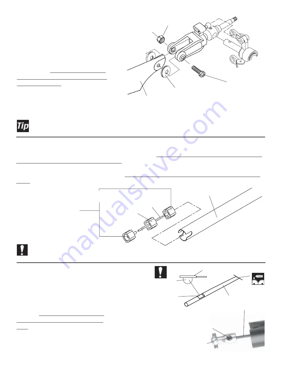
Century Helicopter Products CN1076 Скачать руководство пользователя страница 18

18

#HI6099
Tail Rotor
Blades x 2

M3x20 Socket
Cap Screw x 2

M3 Locknut x 2

After flying the model, if a vibration is noticed on the horizontal fin, you can remove the complete tail rotor
assembly with the hub and further balance it using a High Point balancer.  Careful sanding of the rotor
blades is all that is needed.

Leading Edge

Snap the ball on the tail rotor grip into the
adjoining pitch slider link on both sides.
Install the tail rotor blades shimmed with
M3x10 plastic washers on both sides using
two M3x20 socket cap screws and M3
locknuts.  Note the direction of the blades
on the diagram, the leading straight edge of
the blade should be on the same side as the
ball on the blade grip.  To tension the blade
bolt, start loose and tighten until the blade
holds horizontal but pivots freely when
moved.

Step 29  Tail Blade Assembly

#HI3096A
M3x10 Plastic
Washer x 4

Insert three tail drive shaft guides on to the brass tail drive housing (note that one guide has a larger center hole than the
others, slide this one to the center of the brass tube),  add the remaining two onto the ends.  Glue the guides into posi-
tion using Zap Ca on the brass tube.  Insert the tail shaft guide assembly into the tailboom from the end with the 2 holes
and position the assembly centered in the tailboom ( gentle tapping with a wooden dowel will easy the insertion of  the
guides ).

#HW3063A
Tail Drive Shaft Set

#HW3062A
Tail Boom

Drive
Housing
( brass )

Drive Housing
Ends x 2

Make sure the brass tubing is glued to the plastic guides inside the tail boom.

Step 30  Tail Drive Shaft & Pushrod Guides

Drive Shaft
Support
Center x 1

Step 31  Tail Drive Shaft

#HW3063A
Tail Drive Shaft Set

Deepen the flat spot on
the the round end of the
Tail Drive Shaft.

File

Tail Drive Shaft

Apply Grease

For extra security, continue filing until the flat
spot is 1/3

rd

 the thickness of the shaft. Thor-

oughly grease the tail drive shaft (Tip 1) and
insert the newly filed end into the tailboom end
with the slots into the drive shaft housing
assembly (ensure the end with the new flat
spot exits the tailboom end with the round
holes) and degrease both ends of the shaft.
Attach the universal tail drive coupler using
two M4x4 set screws using locktight.

#CN1076-12
Tail Drive Coupler - Male

M4x4 Set
Screw x 2

Содержание CN1076

Страница 1: ...licopter Instruction Manual F F F F F GELCOAT FIBERGLASS FINISH F F F F F CRYSTAL CLEAR WINDSHIELD F F F F F SCALE WIRE LANDING GEAR F F F F F SCALE ELEVATED TAIL BOOM F F F F F ENGINE SIZE 50 F F F F F MAIN ROTOR DIAMETER 58 F F F F F HEIGHT 19 F F F F F LENGTH 47 FEATURES Photo shows optional accessories installed ...

Страница 2: ... that if you are in doubt of your abilities seek assistance from experienced radio control helicopter modelers and associations As the manu facturer we assume no liability for the use of this product Pre assembly Information Upon opening the kit all the major component parts are packaged in bags to correspond to specific sections of the manual greatly facilitating assembly Various assemblies have ...

Страница 3: ...supplied in kit 3 0mm Appropriate Socket Wrench glow plug wrench for engine shaft nut Hobby Scissors clear tape masking tape Double Sided Foam Tape 1 16 3 32 Foam Rubber radio packing JB Weld Goop or Zap a Dap a Goo Thread lock liquid e g Locktite Hobby Grease Super Lube Oil to lubricate sliding shafts Tri Flow Recommended Tools Accessories Symbols used to help assist you in building the kit Apply...

Страница 4: ...medium CA glue to the back side of the bearing cup to secure to the offset plate Insert one ball bearing into each tie bar Insert one M3x6 button head screw throughtherightsideholeoftheoffset plate into one tie bar Make two identical sub assemblies Note that the bearing cups face outwards from the head block Insert one M3x15 button head screw through the tie bar bearing slide one steel spacer and ...

Страница 5: ... ball on the bell mixer Make sure both pushrods are the same length Step 3 Main Rotor Grip Assembly Insert the slide tube into the bell mixer arm from the offset side through the oilitebearings installedalready and secure onto the blade grip with one M3x16 Socket Cap screw and M3x7 Flat washer Install one long ball and one short ball Tip 2 into the Bell Mixer File the bolt flush to the inside of t...

Страница 6: ...ssembly together the tapered standoff needs to be held with pliers while tightening the button head screw Loosely tighten the M4x5 Set Screws into the round aluminum inserts Using a ruler check the distance between the end of the flybar and the control arm and adjust until the lengths are the same Remove each M4x5 Set Screw and locktight in place over the flat spots on the flybar Slide the FlybarW...

Страница 7: ...from the flat side of the arm Using one slide tube inserted from the flat side secured using one M3x16 Button Head Screw and one 3x7mm Flat Washer per arm Do not overtighten the arm as it is threaded into the plastic washout base Also note the screw is attached on the left when installed later on the main shaft Press the radius link on to the inner short balls on the swashplate HI3152C WashoutArm ...

Страница 8: ...shaft before the hex coupler is attached Apply somelubricantontheshaftafterassemblytoensure smoothverticalmovementinsidetheinnerracesofthe bearingswhenengaginganddisengagingthestart system Position the M5 collar so the end of the start shaftclearsthefan verifyafterinstallingthelower frames CN0402 Hex Start Adapter M4x4 Set Screw x 2 med hex key M3x4 Set Screw small hex key Hex Starter Extension Op...

Страница 9: ...w Tip1 into theAlloy Drive Gear and tighten in place using threadlock Test fit the gear assembly into one half of the upper sideframes Whileholdingthepiniongear trytoslide the counter gear up and down on the shaft The gear should not slide up the shaft if it does readjust the top pinion to remove the slop and re tighten the set screw using threadlock It is important that there is no free playbutth...

Страница 10: ...p them from getting lost Do not apply threadlock here HW3059A Tail Transmission Output Shaft M3x4 Set Screw small hex key Step 13 Universal Coupler Tail Pinion Gear CNBB1350 5x13 Ball Bearings x 2 HW3057 Tail Rotor Output Gear HW3059A Tail Shaft Spacer HI3154 Universal Tail Drive Coupler M4x4 Set Screw med hex key Insert one M4x4 Set Screw Tip 1 using threadlock into the gear make sure the set scr...

Страница 11: ...stopper on the main shaft followed by one M10x19 Ball Bearing and one M14x19 Spacer the spacer must be installed on top of the bearing Slide one M8x19 Ball Bearing onto the bottom of themainshaft Align the right ccpm side servo mount over the holes for the starter shaft assembly observe the correct direction of the block assemblies and insert four M3x12 SelfTapping Screws1 to secure it in place Po...

Страница 12: ...N on the main shaft make sure the main gear rotates push the mast stopper against the upper ball bearing apply threadlock to the set screws and tighten in place HI3107 Upper Side Frames L R M4x4 Set Screw x 2 HW3115B CCPM Servo Mount Right HW3115B Servo Mount Brace Attach the servo mount brace using four M3x10 Socket Cap Screws and M3 Locknuts through the holes on the CCPM Servo Mounts Look at the...

Страница 13: ...e M3x7 flat washers then insert through the upper side frames securing with one M3 locknut Insert one M3x35 socket cap screw through the frontmost upper hole in the tail boom clamps then through the center hole of the ccpm servo mount and insert secure with one locknut on the other side Attach the tail boom clamps using four M3x8 socket screws inserted into the top holes of the mounts using thread...

Страница 14: ...from the inside of the fan assembly Again only torque the nut 1 16th more HI3009 Cooling Fan M5x13 Flat Washer Engine Nut Optional Parts CN2153 Throttle Extension for OS50SX H M3x16CS Machine Screw x 4 Engine Assembly with Fan Secure the engine assembly on to the engine mount make sure the mount is installed with the engine mount holes closest to the bottom of the engine notice it is recessed for ...

Страница 15: ...ep 20 R L Attach the right lower frame R to the upper frame assembly with two M3x12 Socket Cap Screws Tip 1 and M3 Washers using threadlock Slide the cooling Fan Shroud over the engine head and position the engine assembly into the upper frames while attaching the two M3x12 Socket Cap Screws and large M3x11Washers through the R side frame leave these loose for now into the engine mount Make sure t...

Страница 16: ...lide the SpacerTube onto the shaft and positionagainstthegear 2x12mm Pin HW3073 Tail Rotor Drive Shaft HI3075 Small Bevel GearA M3x4 Set Screw small hex key HW3074 Spacer Tube Hole through shaft Step 24 Tail Output ShaftAssembly HI3089 Tail Pitch Ball Links x 2 M2x8 Pin x 2 Thetailpitchplateandtail pitch ball links are pre assembled Note apply some JB weld to the outside of the lock ring to avoid ...

Страница 17: ...ake sure the bearing is fully seated flush into the grip SlidethegripontothetailhubandslideoneM4x9ThrustBallBearing installthefirststeelwasher largerinside diameter followed by the ball race remember to grease the ball race followed by the second steel washer smaller insidediameter followedbyoneM3x5x0 5microwasherandfinallyoneM3x9ThinBallBearing Important apply red threadlock to the threads in the...

Страница 18: ...rass tube add the remaining two onto the ends Glue the guides into posi tion using Zap Ca on the brass tube Insert the tail shaft guide assembly into the tailboom from the end with the 2 holes and position the assembly centered in the tailboom gentle tapping with a wooden dowel will easy the insertion of the guides HW3063A Tail Drive Shaft Set HW3062A Tail Boom Drive Housing brass Drive Housing En...

Страница 19: ...osition the output gear assembly into the right gear box half insure the 2 bevel gears are meshed properly and the ball bearings are fully seated in their recesses and liberally grease the gears before closing the gear box Position the gear box halves over the holes in the end of the tail boom and secure with one M3x10 socket cap screw and M3 locknut at the end of the gearbox one M3x12 socket cap ...

Страница 20: ...tcontrolstheccpmmixingforthe3cyclicservos Reviewing theradioinstructionswillassistyouinbecomingfamiliarwiththefunctionsthataffecttheindividualservosandaffectthe interaction of the three servos working together to control the swashplate Radio Setup Procedure 1 It is best to choose a new model memory if available and use the Reset feature to remove any previous settings or mixes rememberthisusuallya...

Страница 21: ...ldimensionsareinmillimetersandaremeasuredfromthe centers of the control balls or ball ends HI3145 Ball Link Set CN1076 21 Long Rotor Head Pushrod Set Due to the different types of radio and servos that arechosentoinstallintothehelicopter match each pushrod to the lengths in the table for optimumsetup A B I C D E G OptionalPart CN2255 Control Rod Setup Gauge Easily duplicates pushrods by attaching ...

Страница 22: ...efinaladjustments Note Itisveryimpor tant that before you install the pushrod linkages that you first charge your radio then remove all the servo horns from the servos and center all the mechanical or electronic trims on the radio After the rotor head pitch curves are setup tighten the single M3x4 set screw that holds the metal washout guide in place so that there is a 1mm space between the top ed...

Страница 23: ...ide to side The swashplate will also travel up and down as three servos work together This will result if the items in Step 33 have been followed and theATVfunction for the three ccpm servos has been set very very accurately to eliminate pitch change when moving the aileron or elevator sticks Thiswillbecomeobviousinthenextsteps Afterinstallingthethreecyclicpushrods the swashplateshouldsitlevel CCP...

Страница 24: ...ar servo horn parallel to the body of the servo and the CCPM Rear E Pushrod Similarly attach the front servo horns mounted 90 degrees to the servo with the CCPM Front D Pushrods Movethecollectivesticktoitsmaximumpositionandwatchforanyroll aileron orpitch elevator inputs Ifaninputis found the problem will be one of the following in the table The table describes the symptom and the steps to correct ...

Страница 25: ...the long pushrod and thread the rudder pushrod connector onto the straight end Next thread the 105mm pushrod into the connector and attach one black ball link to the end Position the tail pushrod guides to allow for a very smooth rudder pushrod align ment you should be able to move the pushrod very easily Connect the ball links and reduce theATVor EPAsettings in theradiotoavoidbindingthepitchplate...

Страница 26: ...nthecarburetorclosescompletelytoshuttheengineoff Also check that in the high position the carburetor is fully open If necessary use theATVor EPAadjustment to limit the servotraveltoavoidbindingthelinkageatthefullopenandfullclosedpositions Shut Down Trim full down Carb closed 0 Idle Trim at Middle Carb open 1mm Hover 50 Carb half open 100 Full Power Carb full open Throttle Servo CN1076 22 Throttle ...

Страница 27: ...flector is used to keep the gases awayfromtheinsideofthecabin 14mm 16 10 R8mm Bottom Right Edge of Cabin Step 41 Fuel Filter Cutoff If you have not completed the fuel lines do so now and connectthepickupline withclunkattachedinsidefuel tank toafuelfilter optional andthenconnectthefilterto thecarburetorfuelinletjustbelowtheneedlevalve Connect the vent line tube to top of fuel tank to the pressurefi...

Страница 28: ...il boom clamp Tightenthelowerscrewsuntilthetailboomwill not rotate in the clamps but do not overtighten the clamps Attach both ball links Rotate the guidesuntilthepushrodmovesverysmoothat thedistanceslisted thenbondtheguidesin place with a few drops of CA adhesive Let completelydry M4x4 Set Screw x 2 HI3106ATail Pushrod Guides x 3 7 3 4 14 21 1 5mm Tail boom positioned 1 5mm past the 2nd tail boom...

Страница 29: ... The average beginner will spend the better part of a month to apply a good clean paint job Preparing the fuselage for painting After opening the fuselage examine all the fiberglass components to see where work needs to be done to allow a simple bring up of the fuselage Bring up describes the necessary steps to complete all the jobs in order to start priming the fiberglassparts Typicalworkthatisdo...

Страница 30: ...smallcircles untiltheholeisatthesizewanted 5 Primingthefuselageaccomplishestwotasks firstly theprimerpaintisdesignedtoaggressivelyadheretothesurface being painted and provide the best surface for the colored paint to adhere to secondly all surface imperfections will become visible Depending on the particular imperfection light sanding with number 600 or 800 sand paper and the secondprimingwilltake...

Страница 31: ...r of the cabin The plastic will need to be bonded with a solvent type of adhesive Once dry the parts can be paintedwithplasticcompatiblepaint Trim to fit front inside radius of cabin CN1076A Instrument Panel Set Joint between panel parts STEP 46 Windshield Test a black marker on some of the scrap material and make sure it can be removed with rubbing alcohol Trace the moldlineinthewindshieldandthen...

Страница 32: ...dinglightlensesandthe domes The domes should be painted silver on the inside but do not paint the mating surface between the dome and the lense Apply goop to the outside edge of the lense and bond tothelandinglightbezel Afteritdrys bondthefinisheddomes directly on top of the lenses CN1076 2 Landing Light Domes CN1076 2 Landing Light Bezel CN1076 2 Landing Light Lense STEP 50 Landing Light Installa...

Страница 33: ...rhere Aftermarking drillallholesusinga1 16 1 5mm drillbitthroughboththecabinandthefairing Removethefairingandbondthematchingwooden squaresagainstthebottomofthefairingusingepoxy After completelydry re drillthesixholesusinga3 32 2 4mm drillbitandusingonescrew tapallholesaheadoftime Finally the wooden blocks can be painted to match the inside color of the cabin Theantennaholeneedstobedrilledcarefully...

Страница 34: ...Landing Gear Mounts Slide one M3x12 socket cap screw from belowthelandinggear insertoneM3x9x4 plasticspacerthencontinuethroughtherear holeonthemainmechanicsandsecureusing one M3 locknut CN1076 20 M3x9x4 Plastic Spacer x 2 M3x12 Socket Cap Screw x 2 M3 Locknut x 2 STEP 56 Cabin Grommets Insert one large grommet into each upper side hole and bond in place using Goop or similaradhesivebyliftingtheins...

Страница 35: ...pperusingthreadlock Lift the shroud and connect the plastic washout links to the short steel balls on the inner race of the swashplate and the long C pushrods to the long balls on the inner race CN1076 19 Front Landing Gear Brackets x 2 STEP 58 Cabin Installation Loosen and remove the two front M3 locknuts from the landing gear use the 5 5 nut driver for access Tip the cabin forward and slide over...

Страница 36: ...M4x4 Set Screws The problem is a result of the set screws not havingthesametension HW3070 Tail Input Shaft HI3075 Large Bevel Gear CNBB513 Bearing x 2 M4x4 Set Screw x 2 Tail boom will just overlap the edge of the tail gear box STEP 59 Receiver Rx Battery Mounting The receiver and the receiver battery pack should be mountedinthebottomofcabinallthewayinthefront to balance the helicopter Underneath ...

Страница 37: ... Screw inserted through the mount and secure with one M3 Locknut Notice that the tail pitch bellcrank is positioned on the top of the tail gearbox that matches up with the tail pushrod as it exits the fiberglass tail boom Also not the tail rotor is mounted on the left side of the helicopter In this configuration as the rudder pushrod is movedforwardthehelicopter snosewillturnlefttotheleft CN1076 6...

Страница 38: ...s mark and drill two 1 8 3mm holes and attach the strap to the top of the shroud using one M3x8 Phillips screw through the strap the shroud insert one M3x7 flat washer and secure with the M3 locknut The last step is to remove the M3x35 Socket screw from the lower tail boom clamp and capture the spring into the slot Gently grab the spring with pliers and replace the screw Note in the future when re...

Страница 39: ...izontalfinand the matching outside surface stub on the other side of the vertical fin Using goop or Epoxy apply adhesive to the stub slide the horizontal fin in place and hold in position using tape wrapped from the end of the horizontal fin to both the top andbottomoftheverticalfin Aftercompletelydry tapthetwoholesformountingthefinassemblyusinganavailable M3x12SelfTappingScrew Followthebendingdia...

Страница 40: ...only be achieved through adjusting the individual values which control the pitch and throttle at a given stick position Dual Rates For beginners using the flybar weights the dual rate values should be set at 100 for both switch positions until hovering has been mastered Normal position high rate 100 Switch position 1 low rate 75 Now that the servo installation into the helicopter is finished the f...

Страница 41: ...training pod is strongly recommended to assist in learining to hover the helicopter with substantially reduced risk of crashing These systems provide an on ground training capability to allow pilots to become familiar with the helicopter before actually leaving the ground Pitch Once the helicopter is flying the pitch settings have to be fine tuned Using appropriate training gear increase the throt...

Страница 42: ...provide a starting point for the beginner These values correspond to the total travel for the tail rotor pitch To adjust the high setting hold the helicopter at hover and increase the throttle so the helicopter climbs steadily Notice the direction the nose rotates High Stick Setting 40 Low Stick Setting 20 Normal Flight Mode left increase revo value to increase tail pitch right decrease revo value...

Страница 43: ...opter move the rudder left and the nose will move left 3 Start by increasing the throttle slowly until the helicopter rises 2 6 inches off the ground then set it back down 4 Repeat this process until you become comfortable with the holding the model in the same spot for a few seconds then land it After some time at this you can increase the height slightly up to 1 foot be very carefull not to get ...

Страница 44: ...rple CN0402 Hex Start Adapter w set screw 5mm 1 CNLR1000S Ball Links 2mm Grey Tail Pushrod 10 CNLR1003 Micro Washer 3x5x0 5T 10 CNLR1013 Black M2 Steel Ball Short servos 2 CNLR1014 Stainless M3 Steel Ball Short bell mixer arms 2 CNLR1015 Stainless M3 Steel Ball Med washout arms 2 CNLR1016A Stainless M3 Steel Ball Long bell mixer 2 CN2403 Hurricane 660mm Sym Carbon Main Blades pair R22 1 CN2405 Hur...

Отзывы: