background image

Page 10

SKU 97080

For technical questions, please call 1-800-444-3353.

Connect a high pressure air hose (not included) to the Pressure Regulator (24). 

1. 

Connect an air blow gun (not included) to the other end of the air hose. Turn the 
compressor on. Refer to Hose Connection Instructions on page 8.

When  the  maximum  air  pressure,  100  PSI,  is  reached  as  indicated  by  the Tank 

2. 

Pressure Gauge (26), the motor will stop. 

Blow air out of the blow gun while you turn the Pressure Regulator (24) knob 

3. 

to adjust Pressure Regulator (24).  Turn the Pressure Regulator (24) knob 
counterclockwise to decrease the PSI, turn it clockwise to increase the PSI. 
When the Regulated Pressure Gauge (70) shows the pressure that you want to 
limit the compressor to, the Pressure Regulator (24) is set. 

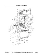
(See Figure C.)

Between the Pressure Regulator knob and valve body, a narrow ring acts as a 

4. 

lock-ring for the knob. Rotate the ring in a counterclockwise direction and tighten 
it against the knob to secure the setting.  

(See Figure C.)  

NOtE

:  When the maximum air pressure, 100 PSI, is reached as indicated by the 

Tank Pressure Gauge (26), the motor will stop.  The Compressor will automatically 
restart when the air pressure drops below 85 PSI.  

(See Figure C.)

to Stop the Compressor:

Push the ON/OFF Power Switch (45) to its “OFF” position.  

1. 

Unplug  the Air  Compressor  from  its  electrical  outlet.  Place  a  collector  can  (not 

2. 

included) under the Air Tank (53) and turn the Drain Valve (54) counterclockwise.

Pull  out  on  the  Safety  Valve  (25)  to  release  all  remaining  air  pressure  from  the 

3. 

Air Tank (53). 

 (See Figure C.)  

This will not only drain the air, but will also drain 

any  accumulated  moisture.   After  all  air  is  drained,  turn  the  Safety  Valve  (25) 
clockwise.

Squeeze the trigger on the pneumatic tool to release any remaining air pressure 

4. 

from the tool.  Then disconnect the air hose from the tool, and store the tool in a 
clean, dry, safe location out of reach of children. 

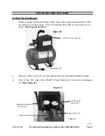
Remove any moisture in the Air Tank (53) by opening the Tank Drain Valve (54).  

5. 

Then, retighten the Drain Valve (54).  

(See Figure b.)

Allow the Air Compressor to completely cool.  Then store the unit in a clean, dry, 

6. 

safe location out of reach of children.

REV 07k

to Adjust the Air Regulator:


Содержание 97080

Страница 1: ...hts reserved No portion of this manual or any artwork contained herein may be reproduced in any shape or form without the express written consent of Harbor Freight Tools Diagrams within this manual ma...

Страница 2: ...Write the invoice number on the inside of the front cover Keep this manual and invoice in a safe and dry place for future reference GENERAL SAFETY RULES AND PRECAUTIONS WARNING READ AND UNDERSTAND ALL...

Страница 3: ...bles better control of the air tool in unexpected situations Use safety equipment Always wear ANSI approved safety impact 6 glasses dust mask respirator and hearing protection during use TOOL USE AND...

Страница 4: ...D breathing as described in Compressed Gas Association Commodity Specification G 7 1 1966 OSHA 29 CFR 1910 134 and or Canadian Standards Associations CSA In the event the Air Compressor is used for th...

Страница 5: ...authorized people to handle or play with the Air 15 Compressor Do not modify the factory set pressure shutoff or startup switches This tool will do 16 the work better and safer at the speed and capaci...

Страница 6: ...ave a three wire cord and three prong grounding plug The plug must be connected to a properly grounded outlet If the tool should electrically malfunction or break down grounding provides a low resista...

Страница 7: ...ing or broken please call Harbor Freight Tools at the number shown on the cover of this manual as soon as possible ASSEMBLY INSTRUCTIONS CAUTION 1 Always make sure the Compressor s Power Switch 45 is...

Страница 8: ...in line shutoff valve is an important safety device because it controls the air supply even if the air hose is ruptured Note If an automatic oiler system is not used add a few drops of Pneumatic Tool...

Страница 9: ...closed Pull on the Safety Valve 25 to verify that it is not stuck See Figures B and C Plug the Power Cord 35 into the nearest 120 volt grounded electrical outlet 2 Push in the ON side of the ON OFF Po...

Страница 10: ...OTE When the maximum air pressure 100 PSI is reached as indicated by the Tank Pressure Gauge 26 the motor will stop The Compressor will automatically restart when the air pressure drops below 85 PSI S...

Страница 11: ...inspect the general condition of the Air Compressor Check for loose screws misalignment or binding of moving parts cracked or broken parts damaged electrical wiring loose air fittings and any other c...

Страница 12: ...gulator 1 25 Safety Valve 1 26 Tank Pressure Gauge 1 27 Two Way Valve 1 29 Muffler Board 1 30 Screw M3 x 6 4 31 Copper Connector Rod 2 32 Copper Hoop 2 33 Screw M6 x 25 4 Part Description Qty 34 Dampi...

Страница 13: ...Page 13 SKU 97080 For technical questions please call 1 800 444 3353 ASSEMBLY DIAGRAM 70 26...

Страница 14: ...purchase date and an explanation of the complaint must accompany the merchandise If our inspection verifies the defect we will either repair or replace the product at our election or we may elect to...

Отзывы: