background image

Page 18

SKU 45656

For technical questions, please call 1-800-444-3353.

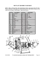
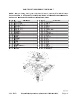
pARTS lIST/ASSEMBlY DIAGRAM B

NOTE:  When referring to the parts listed/shown below, include the letter “B” after 

the part numbers.  Some parts are listed and shown for illustration purposes only, 

and are not available individually as replacement parts.

part #

Description

part #

Description

 1B

 Front panel

 19B

 Seeger ring

 2B

 Body

 20B

 Spring

 3B

 Side cover

 21B

 Rubber ring

 4B

 Nut

 22B

 Rubber support

 5B

 Washer

 23B

 Screw

 6B

 Screw

 24B

 Arm

 7B

 Cylinder body

 25B

 Screw

 8B

 Fitting

 26B

 Washer

 9B

 V-seal

 27B

 Shovel

 10B

 Piston

 28B

 Hand grid

 11B

 Washer

 29B

 Rubber support

 12B

 V-seal

 30B

 Screw

 13B

 O-ring

 31B

 Rubber support

 14B

 Lid

 32B

 Rotating pin

 15B

 Bead-breaker rod

 33B

 Nut

 16B

 L-union 1/4”

 34B

 Oil box

 17B

 Screw

 35B

 Complete Cylinder

 18B

 Pin

 36B

Safety valve

Содержание 45656

Страница 1: ...ks Blvd Camarillo CA 93011 Visit our website at http www harborfreight com Read this material before using this product Failure to do so can result in serious injury Save this manual Copyright 2001 by Harbor Freight Tools All rights reserved No portion of this manual or any artwork contained herein may be reproduced in any shape or form without the express written consent of Harbor Freight Tools F...

Страница 2: ... number on the inside of the front cover Keep this manual and invoice in a safe and dry place for future reference SAFETY WARNINGS AND PRECAUTIONS 1 KEEP WORK AREA CLEAN AND DRY Cluttered damp or wet work areas invite injuries 2 KEEP CHILDREN AWAY FROM WORK AREA Do not allow children to handle this product 3 STORE IDLE EQUIPMENT When not in use tools and equipment should be stored in a dry locatio...

Страница 3: ...parts and any other conditions that may affect the operation of this tool Replace or repair damaged or worn parts immediately 11 REPLACEMENT PARTS AND ACCESSORIES When servicing use only identical replacement parts Only use accessories intended for use with this product Approved accessories are available from Harbor Freight Tools 12 MAINTAIN THIS PRODUCT WITH CARE Keep this tool clean and dry for ...

Страница 4: ...en carbon dioxide combustible gases or any other bottled gas as a power source for this tool 3 WHEN CONNECTING TO THE AIR SUPPLY A Wrap approximately 4 of Teflon tape around the male threads of a Quick Connector not provided Then wrench tighten the Quick Connector into the Pressure Regulator 5F See Figures A C and E B If an automatic oiler is not used add two drops of oil into the Quick Connector ...

Страница 5: ...meplate Amperes Extension Cord Length 25 50 75 100 150 200 0 5 16 16 16 14 12 12 5 1 8 16 16 14 12 10 8 1 12 14 14 12 10 12 1 15 12 12 10 10 15 1 20 10 10 10 FIGURE D 7 TO AVOID PERSONAL INJURY AND OR PRODUCT DAMAGE ALWAYS MAKE SURE THE TIRE RIM IS FIRMLY SECURED ON THE TIRE CHANGER WITH THE JAWS 17C SEE FIGURE E AND ASSY DIAGRAM C 8 NEVER PLACE YOUR HANDS BETWEEN THE VEHICLE WHEEL RIM AND THE JAW...

Страница 6: ... Assembly Diagrams pages 17 through 22 are included If any parts are missing or broken please call Harbor Freight Tools at the number shown on the cover of this manual as soon as possible PRODUCT DESCRIPTION Prior to using the Tire Changer it is recommended that you study and familiarize yourself with the main components of the unit See Figure E ...

Страница 7: ...hich is on the air water separator D located right side of the base assembly 4 Electric at connection Before making any electric link up check to be certain that the main voltage corresponds to what is stamped on the voltage tag It is absolutely essential that the system is equipped with a good grounding circuit 5 WARNING The Tire Changer requires the assembly of a UL CSA or CE listed 220 Volt 3 P...

Страница 8: ...a 3 counterclockwise direction Press the Bead Breaker Pedal 26E to activate the Paddle 7B When the 4 Pedal is released the Paddle should return to its original position Press the Jaw Clamp Pedal 26E once to open the four Jaws 17C Press the 5 Pedal again to close the Jaws LOCKING LEVER NOZZLE AIR GAUGE 4F TRIGGER FIGURE G 6 Press the Trigger on the Air Gauge 4F to release air from the Nozzle See Fi...

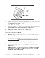
Страница 9: ... Steps for the other side of the wheel tire To Remove The Tire From The Wheel 1 WARNING Before carrying out this procedure deflate the tire fully and remove all the wheel weights 2 Spread tire grease or a similar lubricant liberally on the complete circumference of the broken tire bead NOTE Failure to lubricate the tire bead may cause serious damage to the bead 3 Place the wheel tire evenly on the...

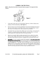
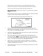
Страница 10: ...g Head 15A rests next to the wheel rim and on top of the tire Then lock the Tools Shaft in position using the Block Support 7A See Figures E and I 6 Insert the Lever 1F between the tire bead and the front section of the Mounting Head 15A See Figures E and I 7 Move the tire bead over the Mounting Head 15A by pulling upward on the Reverse Pedal 59E NOTE To avoid damaging the inner tube if there is o...

Страница 11: ...eel rims of the same size it is not always necessary to lock and unlock the Tools Shaft 13A Instead move the Swinging Arm 5A sideways with the Tools Shaft locked See Figure E 5 TOOLS SHAFT 13A MOUNTING HEAD 15A FIGURE J Move the tire so that the bead passes below the front section of the Mounting Head 15A and is brought up against the edge of the rear section of the Mounting Head See Figure J 6 Ke...

Страница 12: ...air pressure frequently Never inflate a tire above or below the air pressure recommended by the tire manufacturer 2 VALVE LOCKING LEVER FIGURE K AIR GAUGE NOZZLE 4F To inflate the tire attach the Air Gauge Nozzle 4F to the tire valve stem with the Locking Lever in the UP position Check to make sure the Nozzle is pressed down completely over the threads of the valve stem See Figures G and K 3 When ...

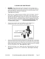
Страница 13: ...e or vibration occurs disconnect the Tire Changer from its air and electric supply sources immediately and have the problem corrected before further use Do not use damaged equipment See Troubleshooting guide 3 At least once per week clean the Turntable 1C with detergent or a nonflammable solvent Also grease the Jaw Guides 17C 4 At least once per month check the oil level in the Lubricator Tank If ...

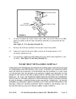
Страница 14: ...d on the left side of the Body Assembly by unscrewing the four Screws Tighten the Belt using the Adjusting Screw located on the Motor Support See Figures F M and Assy Diagram D 7 In the event the Block Support 7A doesn t lock the Tools Shaft 13A in place or the Mounting Head 15A doesn t rise at least 1 8 above the wheel rim which is necessary for working adjust the Nuts as shown in Figure N ...

Страница 15: ...gure O and Assy Diagram E PLEASE READ THE FOLLOWING CAREFULLY THE MANUFACTURERAND OR DISTRIBUTOR HAS PROVIDED THE PARTS DIAGRAM IN THIS MANUAL AS A REFERENCE TOOL ONLY NEITHER THE MANUFACTURER NOR DISTRIBUTOR MAKES ANY REPRESENTATION OR WARRANTY OF ANY KIND TO THE BUYER THAT HE OR SHE IS QUALIFIED TO MAKE ANY REPAIRS TO THE PRODUCT OR THAT HE OR SHE IS QUALIFIED TO REPLACE ANY PARTS OF THE PRODUCT...

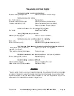
Страница 16: ...place Jaws Defective Piston 26C Replace Plate Cylinder Gaskets 23C Tool touches the wheel rim during tire mounting removing process Locking Plate 12C incorrectly Adjust or replace Locking Plate adjusted or defective Plate Locking Screw 14C loose Tighten Screw Bead Breaker Pedal and Jaw Clamp Pedal lock out of position Return Spring 24E broken Replace Spring Bead breaking operation difficult Silenc...

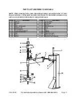
Страница 17: ...ion purposes only and are not available individually as replacement parts Part Description 1A Arm Pin 2A Washer 3A Nut 4A Hand Grid Adjuster 5A Swinging Arm 6A Locking Block 7A Locking Block Support 8A Hand Grid Adjuster 9A Cap 10A Cover 11A Spring Part Description 12A Locking Plate 13A Tools Shaft 14A Bushing 15A Mounting Head 16A Pulley 17A Pin 18A Washer 19A Column 20A Protection sheet1 21A Pro...

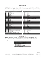
Страница 18: ...ement parts Part Description Part Description 1B Front panel 19B Seeger ring 2B Body 20B Spring 3B Side cover 21B Rubber ring 4B Nut 22B Rubber support 5B Washer 23B Screw 6B Screw 24B Arm 7B Cylinder body 25B Screw 8B Fitting 26B Washer 9B V seal 27B Shovel 10B Piston 28B Hand grid 11B Washer 29B Rubber support 12B V seal 30B Screw 13B O ring 31B Rubber support 14B Lid 32B Rotating pin 15B Bead b...

Страница 19: ... Part Description 1C Turn Table 2C Control Plate 3C Connecting Rod 4C Bushing 5C Seeger Ring 6C Seeger Ring 7C Washer 8C Distributor 9C Washer 10C Screw 12C Plate 13C Washer 14C Screw 16C Slide 17C Jaw 18C U Bolt 19C Piston Assembly 20C Lid 21C Screw Part Description 22C Front Bottom 23C Gasket 24C Nut 25C Washer 26C Piston 27C Cylinder Barrel 28C Stem 29C V Gasket 31C Rear Bottom 32C Fitting 33C ...

Страница 20: ...own for illustration purposes only and are not available individually as replacement parts Part Description 1D Gearbox Assembly 5D Washer 6D Screw 10D Motor 11D Washer 12D Nut 13D Cable 14D Pulley 15D Locking Screw 16D Belt 17D Key 18D Pulley 19D Washer Part Description 21D Bottom Cover 23D Bearing 26D Ring Gear 27D Washer 28D Bearing 29D Screw 30D Upper Cover 32D Oil Plug 34D Gasket 35D Bearing 3...

Страница 21: ... Jaw Clamp Bead Breaker Pedals 27E Pedal Shaft 28E Complete Valve Center Chuck 31E O Ring 32E Valve Shaft Part Description 33E Spacer 34E Screw 36E Silencer 37E Connector 38E L Union 39E Valve Block 40E Air Hose 41E Complete Valve Bead Break 42E Pin 43E Valve Shaft 44E Valve Block 45E T Union 46E Connector 47E Air Hose 48E Air Hose 49E Nut 50E Washer 51E Screw 52E Washer 53E Connecting Rod 54E Scr...

Страница 22: ...Page 22 SKU 45656 For technical questions please call 1 800 444 3353 ASSEMBLY DIAGRAM E REV 03 03 ...

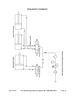
Страница 23: ...Page 23 SKU 45656 For technical questions please call 1 800 444 3353 PNEUMATIC SCHEMATIC ...

Страница 24: ...ts travel and or when the tire bead is broken Rotate the tire slightly and repeat the procedure around the entire circumference of the wheel rim until the bead is completely detached from the rim 3 Lock the wheel on the turntable by depressing the jaw clamp pedal 4 Lower the tools shaft until the mounting head rests next to the wheel rim and on top of the tire Then lock the tools shaft in position...

Страница 25: ...able in a clockwise direction by fully depressing the reverse pedal 10 Continue until the tire is completely separated from the wheel rim And remove the inner tube if there is one 11 Insert the lever between the other side of the tire bead and the front section of the mounting head Move the tire bead over the mounting head 12 Repeat the above steps for the other side of the tire ...

Страница 26: ...rear section of the mounting head 4 When you are working with wheel rims of the same size it is not always necessary to lock and unlock the tools shaft Instead move the swinging arm sideways with the tools shaft locked 1 Lock the wheel rim using the inner part of the jaws 2 Put the tire on the rim 3 Lower the tools shaft until the mounting head rests next to the wheel rim and on top of the tire Th...

Страница 27: ...e grease or a similar lubricant liberally on the complete circumference of the tire bead 10 Move the tire so that the bead passes below the front section of the mounting head and is brought up against the edge of the rear section of the mounting head 11 Keep the tire bead pressed down into the wheel rim channel with your hands or the lever Then depress the reverse pedal to rotate the turntable clo...

Страница 28: ... counterclockwise to unlock it Check the wheel rim and the tire are of the same size And try again 14 Unlock the tools shaft move the swinging arm sideways 15 Inflate the tire with brief jets of air Checking the air pressure frequently Once the proper air pressure has been reached disconnect the nozzle from the valve stem and screw a valve cap onto the stem ...

Отзывы: