Assembly and operating instructions
CENTAX-G
020G-00050…00090-F.10
M020-00009-EN
Rev. 4
CENTA Antriebe Kirschey GmbH
15 / 52
5.1
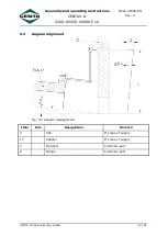
Axial alignment
Fig. 5-1 Axial misalignment
Item
Info
Designation
Remark
3
Hub
If scope of supply
17
Adapter
If scope of supply
C
Flywheel
Customer part
E
Flange
Customer part
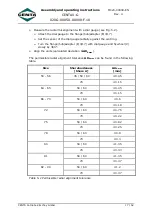
Determine the axial misalignment (see Fig. 5-1).
Take installation length
L
from the installation drawing.
Align the units (installation dimension =
L±∆K
A max
).
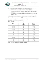
Permissible axial alignment tolerance:
∆K
A max
=
0.5
mm


