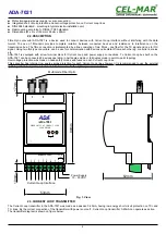
3.3.CONNECTION FIBRE-OPTIC BUS
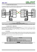
The multimode Fibre-Optic with connectors type: ST®, SC or SMA, connect into their corresponding converter's connectors type: ST®,
SC or SMA like on a figure below. Connecting the fiber optic cables should be cautious and careful not to damage them or dirty. If it is
necessary to lay the cable at an angle, must be created the appropriate bends
Fig 8. Example connection of Current Loop interface devices by the use of FO converters
ATTENTION!!!
The device is equipped in the laser transmitter.
The radiation emitted by the laser transmitter is harmful to the eyes!
Under no circumstances should never look to at the uncovered slot, to which it is not connected the fiber optic connector.
3.4.POWER SUPPLY CONNECTION
The power supply to ADA-7021 converter should be DC (regulated) from 10 V= to 30V=. Nominal power is typically 2W, e.g. HDR-15-
24. Power cable from DC power supplies to device must not be longer than 3m.
Observe the polarity, connect positive (+) of DC power supplies to V+ and negative (-) end to V- terminal. ADA-7021 has the
protection from opposite connection power supply. If after powering on the front panel is not lit green LED PWR, check the
correctness of power connection (polarity).
4. ACTIVATION
Converter can be powered after proper connection according to steps above. If the connection was made properly green LED PWR on
front panel of converter should lit, if not check polarization of power connection. If the red LED RX is lit check correctness of
connection transmitting line of Current Loop Device. The lighting of RX LED indicates no current flow through the optocoupler in the
receiver's circuit.
During proper data transmission through converter the LEDs Tx and Rx should blink.
4.1.LEDS DESCRIPTION
LED
Description
PWR
Signalization of Power Supply
RX
Signalization of data receiving by ADA-7021 from Current Loop.
TX
Signalization of data transmission from ADA-7021 converter through Current Loop
ATTENTION!
AT BAUD RATE ABOVE 38.4 KBPS THE LED'S TX, RX WILL LIT WEAKLY DURING DATA TRANSMISSION
8
ADA-7021
ADA-7021
Passive
Transmitter
V +
V -
Tx+
Tx-
Rx+
Rx-
I1 +
I1 -
I2 +
I2 -
Rx +
Passive
Receiver
Active
Transmitter
Active
Receiver
Tx +
Tx -
Rx -
V -
V +
FO connector
TX
RX
ADA-7021
Active
Transmitter
V +
V -
Power
Supply
V -
V +
Tx+
Tx-
Rx+
Rx-
Current Loop
Device
Current Loop
connector
I1 +
I1 -
I2 +
I2 -
Rx +
Passive
Receiver
Active
Transmitter
Passive
Receiver
Tx +
Tx -
Rx -
FO connector
TX
RX
Current Loop
Device
Current Loop
connector
Current Loop
connector
Current Loop
connector
Power
Supply
Содержание ADA-7021
Страница 11: ...11 ADA 7021...

