Contents
1. GENERAL INFORMATION...................................................................................................................................................................... 3
1.1. WARRANTED INFORMATION....................................................................................................................................................... 3
1.2. GENERAL CONDITIONS FOR SAFE USE.................................................................................................................................... 3
1.3. CE LABEL....................................................................................................................................................................................... 3
1.4. ENVIRONMENTAL PRESERVATION............................................................................................................................................ 3
1.5. SERVICE AND MAINTENANCE..................................................................................................................................................... 3
1.6. PACK CONTENTS.......................................................................................................................................................................... 3
2. PRODUCT INFORMATION..................................................................................................................................................................... 3
2.1. PROPERTIES................................................................................................................................................................................. 3
2.2. DESCRIPTION................................................................................................................................................................................ 4
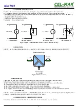
2.3. CURRENT LOOP TRANSMITTER................................................................................................................................................. 4
2.4. CURRENT LOOP RECEIVER........................................................................................................................................................ 5
2.5. ISOLATION..................................................................................................................................................................................... 5
3. INSTALLATION....................................................................................................................................................................................... 5
3.1. ASSEMBLING................................................................................................................................................................................. 5
3.2. CONNECTION TO CURRENT LOOP DEVICE..............................................................................................................................5
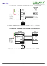
3.2.1. CONNECTION TO DEVICE WITH PASSIVE TRANSMITTER & PASSIVE RECEIVER.......................................................6
3.2.2. CONNECTION TO DEVICE WITH ACTIVE TRANSMITTER & ACTIVE RECEIVER...........................................................6
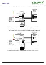
3.2.3. CONNECTION TO DEVICE WITH ACTIVE TRANSMITTER & PASSIVE RECEIVER.........................................................7
3.2.4. CONNECTION TO DEVICE WITH PASSIVE TRANSMITTER & ACTIVE RECEIVER.........................................................7
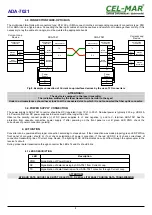
3.3. CONNECTION FIBRE-OPTIC BUS................................................................................................................................................ 8
3.4. POWER SUPPLY CONNECTION.................................................................................................................................................. 8
4. ACTIVATION.......................................................................................................................................................................................... 8
4.1. LEDS DESCRIPTION..................................................................................................................................................................... 8
5. VERSIONS............................................................................................................................................................................................. 9
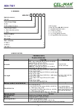
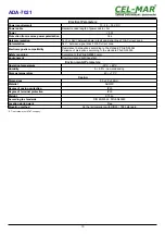
6. SPECIFICATION..................................................................................................................................................................................... 9
2
ADA-7021
Содержание ADA-7021
Страница 11: ...11 ADA 7021...

