3.3. RS485/RS422 BUS
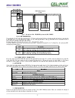
The RS485/RS422 interface is available in the ADA-13040MG on screw terminal block, labelled as: Tx+/A, Tx-/B, Rx+, Rx-.
The ADA-13040MG allows functions on the RS422 and RS485 Bus. Both buses require proper wiring.
3.3.1. CONNECTION TO 4-WIRE RS422 BUS
Before connection 4-wire RS422 Bus, should be set the MODE switch on the front panel of ADA-13040MG in RS422 mode. Connect
wires of bus to terminals TX+/A, TX-/B, RX+, RX-, like below.
Fig 9. Connection of the RS422 device to ADA-13040MG.
3.3.2. CONNECTION TO 4-WIRE RS485(4W) BUS
Before connection 4-wire RS485 Bus, should be set the MODE switch on the front panel of ADA-13040MG in RS485 mode. Connect
wires of bus to terminals TX+/A, TX-/B, RX+, RX- , like below.
Fig 10. Connection of the RS485(4W) devices to ADA-13040MG.
3.3.3. CONNECTION TO 2-WIRE RS485 BUS
Most of the devices with RS485 interface, use 2-wire RS485 Bus for data transmission.
Before connection 2-wire RS485 Bus, should be set the MODE switch on the front panel of the ADA-13040MG in RS485 mode.
Connect wires of bus to the terminals TX+/A, TX-/B, like below.
10
ADA-13040MG
ADA-13040MG
RS485/422
terminal
Vss+
Vss-
Power
Supply
ETHERNET
connector
V -
V +
RJ 45
Tx + / A
Tx - / B
Rx +
Rx -
Device with RS422
RS422
Terminal
GND
Tx +
Tx -
Rx +
Rx -
Rt
Rt
GND
R
S
48
5
(4
W
)
te
rm
in
a
l
G
N
D
RS485/422
terminal
Vss+
Vss-
Power
Supply
V -
V +
Tx+ /A
Tx- /B
Rx +
Rx -
T
x +
/A
T
x -
/B
R
x +
R
x -
R
S
48
5
(4
W
)
te
rm
in
a
l
G
N
D
T
x +
/A
T
x -
/B
R
x +
R
x -
R
S
4
85
(4
W
)
te
rm
in
al
G
N
D
T
x +
/A
T
x -
/B
R
x +
R
x -
Rt
Rt
R
t
R
t
RS485(4W) Network
1200m
ADA-13040MG
ETHERNET
connector
RJ 45
GND


