


PUMP COOLING REQUIREMENTS
10
Pumps are furnished with optional seal chamber jacket, jacketed
casing, jacketed mechanical seal gland, and bearing housing cool-
ing coil according to the pump service.
SEAL CHAMBER COOLING
Cooling is recommended under these conditions:
1) With a mechanical seal when the pumping temperature is
above 350°F. Individual plant specifications may require cool-
ing above 250°F.
Specific applications or liquids may require
cooling at lower temperatures.
2) With a mechanical seal when pumping liquids of 0.75 specific
gravity, or less, when the pumping temperature permits further
cooling.
3) With packing at temperatures above 250°F.
MECHANICAL SEAL GLAND COOLING
Mechanical seal gland cooling is generally applied under the same
conditions as those for seal chamber cooling. For pumping tempera-
tures only slightly above those requiring seal chamber cooling,
gland cooling may not be required on a specific application.
BEARING HOUSING COOLING
Cooling of the bearing housing is applied to cool the lubricating oil
and bearings. At pumping temperatures below 500°F. Such cooling
is rarely necessary. Excessive cooling of the bearing housing may
lead to early bearing failure from moisture condensation contamina-
tion of the oil.
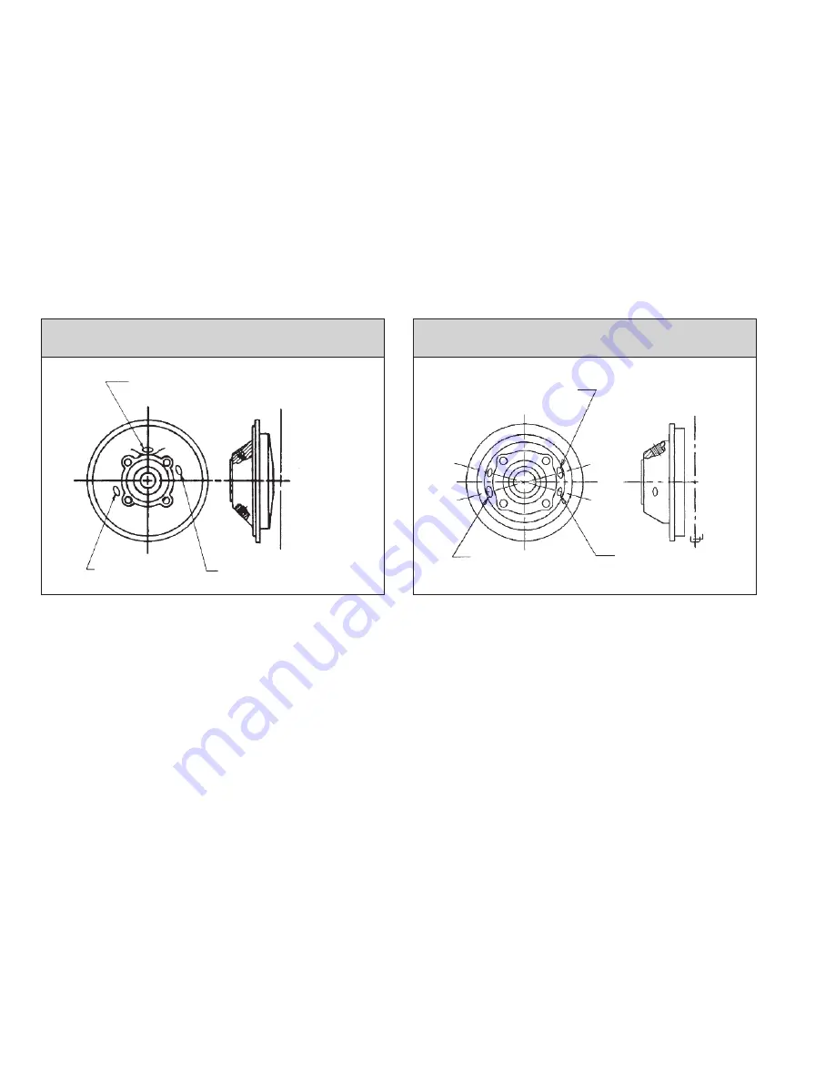
J
ACKETED
S
EAL
C
HAMBER
C
ONNECTIONS
P
H 2110 S
ERIES
P
UMPS
J
ACKETED
S
EAL
C
HAMBER
C
ONNECTIONS
P
H 2140/2170/3170 & 2180 S
ERIES
P
UMPS
INSTALLATION OF COOLING AND/OR SEAL CONNECTION PIPING TO THE PROPER CONNECTIONS IN MANDATORY. PUMP JACKET COOL-
ING WATER INSTALLED TO THE SEAL CONNECTIONS WILL RESULT IN INJECTION OF WATER INTO THE PUMPAGE WHICH MAY CAUSE SERI-
OUS CONTAMINATION OF THE PRODUCT AND HEAVY CORROSION. DEPENDING ON TEMPERATURE, IT MAY ALSO CAUSE A VIOLENT
STEAM EXPLOSION IN THE PUMP OR ASSOCIATED PIPING OR EQUIPMENT WITH EXTREME HAZARD TO PERSONNEL.
IMPORTANT WARNING
COOLING WATER PIPING
The cooling water piping depends on what cooling coil or jackets
are furnished and used. Jackets to be piped in series are Seal
Chamber Cooling, and Bearing Housing Cooling Coil, with the
cooling water to flow in that sequence. Not all of these jackets will
necessarily be used. All other jackets or cooling coil should be piped
in parallel with separate flow to each. The customer must provide
piping and a shut-off valve on each cooling inlet. The customer must
also provide the outlet piping from each jacket or cooling coil, fitted
with a pressure relief valve set at a maximum of 150 psig. and then
a flow control valve.
The relief valve is installed between the jacket and the flow control
valve to relieve any dangerous pressure that could develop in the
jacket. Pipe each outlet from the flow control valve to an open sight
drain or through a suitable flow indicating device into the plant cool-
ing water return system.
In no case should the outlet be piped into the municipal water
system.
Cooling jacket piping should be run to provide inlet water at the low-
est jacket connection and outlet from the highest connection.
COOLING WATER FLOW RATES
Seal chamber jacket cooling
water flow rates are related to pumping
temperature. A rate of 2 to 5 GPM is advisable, the higher rate at a
pumping temperature of 500°F.
Mechanical seal gland cooling
flow should be adjusted to about
1
/
2
GPM.
Bearing housing cooling coil
water flow rate should be adjusted to
1
/
2
GPM. This will maintain the bearing housing temperature in the
120°F to 200°F range. The pump may be operated without bearing
housing cooling if experience in the particular installation shows that
bearing housing temperatures do not rise above 200°F.
3/8” NPT
Seal Connection
1/2” NPT
Cooling Inlet,
Heating Outlet
1/2” NPT
Cooling Outlet,
Heating Intlet
WARNING: SEE
IMPORTANT
WARNING BELOW.
WARNING: SEE
IMPORTANT
WARNING BELOW.
Cooling Outlet,
Heating Inlet
Cooling Inlet,
Heating Outlet
Seal Connection
180° Apart
Discharge Flange


