


36
edge of a few parameters (diameter of wire, material being welded,
type of gas to use) and/or the RUN/MEM key to display the operat-
ing features of the programmes supplied by the manufacturer.
The values of the preset wire speed
(adjustable with EN-
CODER 1 knob) are displayed on the dVPA and the preset weld-
ing voltage
, (adjustable with ENCODER 2 knob) are displayed
on the dVPV before starting to weld.
Set as required and start welding.
The actual weld current
(adjustable with ENCODER 1 knob -
it can vary from the minimum to the maximum of the correspond-
ing synergic curve of the programme) will be displayed on the dVPA
and the actual weld voltage
, (adjustable with ENCODER 2
knob - it can vary from 10 to 40V) will be displayed on the dVPV
during welding.
The parameter on the displays remains unaltered when changing
from the setting to the welding phases and vice versa.
Welding spot settings may also be created and memorized with
this welding procedure (see special paragraphs) and may be back-
tracked in the AUTOMATIC WELDING PROCEDURE programme.
AUTOMATIC welding mode
Press the WELDING PROCESS key and turn to MIG-MAG
,
MIG PULSED
or MIG DUAL PULSED
then press the
WELDING PROCEDURE SELECTION key to AUT to access this
welding mode.
Previously memorized automatic jobs can be backtracked in the
automatic welding mode, you can in fact enter and backtrack pre-
viously set and memorized programmes in the synergic and manual
welding procedures (see special paragraphs). When the settings
of a single preset welding spot have been entered they cannot be
changed unless you change to another welding spot.
Special functions
Just press the SPECIAL FUNCTIONS key to enter these param-
eters. A brief description of parameters that could be changed fol-
lows and all the eventual combinations to be had are summed up
in table 6 (easily legible).
1) STARTING SPEED — Adjusts the starting speed of wire to the
piece. The given value is a variation in percentage against the
values set in the factory (StS - from -30% to +100% with a 1%
interval for adjustment);
2) BURN BACK — Adjusts the length of the wire coming out of
the gas nozzle after welding. The given value is a variation in
percentage against the values set in the factory. A higher number
corresponds to greater wire burn back (bub - from -20% to
+20% with a 1% interval for adjustment);
3) PRE GAS — Supplies a quantity of extra gas, for a given time
set in the factory, before starting to weld (PrG - from 0 to 2
seconds with a 0.1 seconds interval for adjustment);
4) POST GAS — Supplies a quantity of extra gas, for a given time
set in the factory, before finishing welding (POG - from 0 to 10
seconds with a 0.1 seconds interval for adjustment);
5) CRATER START CURRENT — This is the current used to
start welding (CRATER welding mode connected) and may
be adjusted from - 50% to + 99% of the welding current (CSC
- from - 50% to + 99% with a 1% interval for adjustment);
6) INITIAL CURRENT TIME – Time during which the current re-
mains at the initial crater value (active only in 2T CRATER
mode) (SCt - from 0 to 5 sec with an adjustment interval of 0.1
seconds);
7) CRATER END CURRENT — This is the current at the end of
welding (CRATER welding mode connected) and may be ad-
justed from - 99% to + 50% of the welding current (CEC - from
- 99% to + 50% with a 1% interval for adjustment);
8) FINAL CURRENT TIME – Time during which the current re-
mains at the final crater value (active only in 2T CRATER mode)
(ECt - from 0 to 5 sec with an adjustment interval of 0.1 sec-
onds);
9) SLOPE — Slope of current to pass from the "initial crater cur-
rent" level to the welding current level and to go from the latter
to the "final crater current" level. (SLO - from 10 A/s to 500 A/s
with a 5 A/s interval for adjustment);
10) DOUBLE PULSE CURRENT — Determines the percentage
value of the peak and base current of the double pulse. The
value indicated is a percentage variation in + or – compared to
the value of the average welding current set (dPC – from 0 to
+100% with a regulation interval of 1%).
EXAMPLE: Average pulsed current = 120 A - Double pulse
current = 180 A – Base current = 60A when the double pulse
current is set at position 50.
11) DUAL IMPULSE FREQUENCY — Establishes the dual im-
pulse frequency (Fdp - from 0.5 to 5 Hz with a 0.1 Hz interval
for adjustment);
12) SPOT WELD TIME — Time needed for spot-welding (after
pressing the torch key) after which the arc automatically
switches off (SPt - from 1 to 20 seconds with a 0.1 seconds
interval for adjustment).
13) AUTOMATIC CURRENT SLOPE — Slope of the current when
passing from one level to another; useful when employing weld-
ing sequences (ACS – from 5A/s to 500A/s with interval regu-
lation of 5A/s). It also determines the variation speed of the
welding current following regulation by the operator.
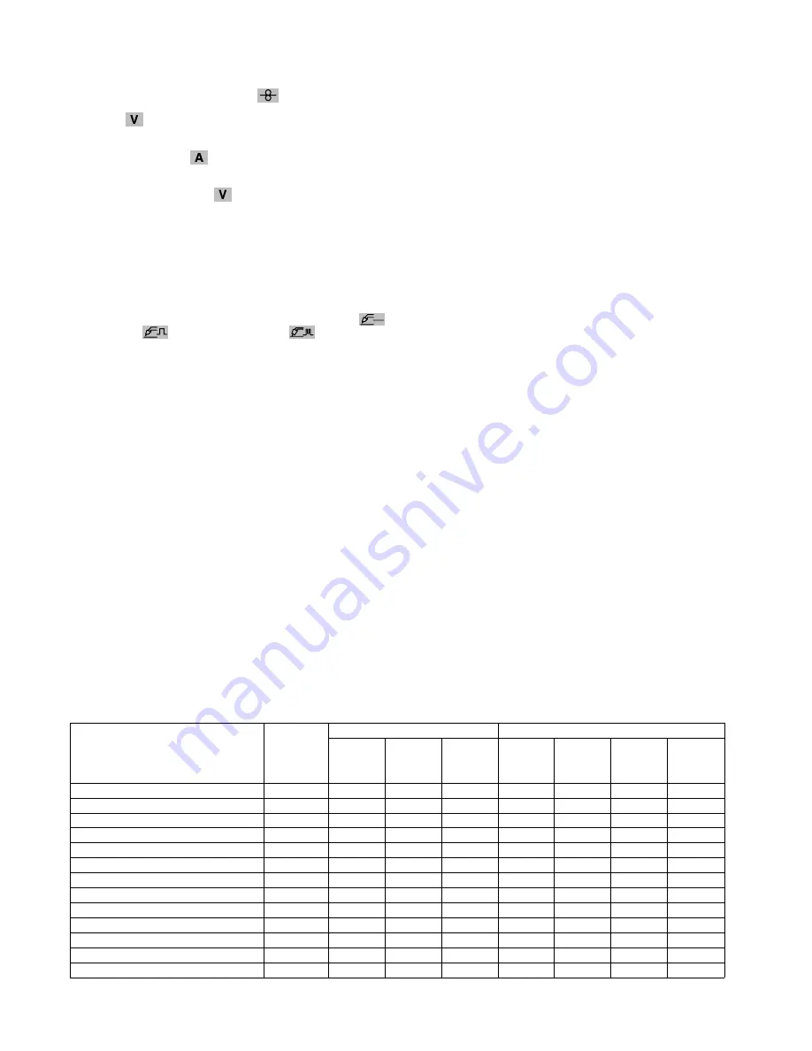
Table 6 sums up the special programmes available in the various
welding modes and processes.
Table 6
✔
✔
✔
✔
✔
✔
✔
✔
✔
✔
✔
✔
✔
✔
✔
✔
✔
✔
✔
✔
WORDING
StS
bub
PrG
POG
CSC
SCt
CEC
ECt
SLO
dPC
FdP
SPt
ACS
STARTING SPEED
BURN BACK
PRE GAS
POST GAS
CRATER START CURRENT
INITIAL CURRENT TIME
CRATER END CURRENT
FINAL CURRENT TIME
SLOPE
DELTA PULSE CURRENT
DUAL IMPULSE FREQUENCY
SPOT WELD TIME
AUTOMATIC CURRENT SLOPE
WELDING MODE
WELDING PROCESS
SIZE
✔
✔
✔
✔
✔
✔
✔
✔
✔
✔
✔
✔
✔
✔
✔
✔
✔
✔
✔
✔
✔
✔
✔
✔
✔
✔
✔
✔
✔
✔
✔
✔
✔
✔
✔
✔
✔
✔
✔
✔
✔
✔
MIG/MAG
MIG
PULSED
MIG
DUAL
PULSED
2T/4T
SPOT
WELD
2T
CRATER
✔
✔
✔
✔
✔
✔
✔
✔
✔
✔
4T
CRATER
Содержание DIGITECH 400 PULSED
Страница 63: ...63...
Страница 67: ...67 A HR26 A A B MMA 2000F800 2000H801...
Страница 68: ...68 C 2000H799 3 D...
Страница 69: ...69 0 D D A 3 2000F800 D...
Страница 71: ...71 DIGITECH 400 PULSED 3 4 5 6 7 8 9 10 1 2 1 2 3 TA4 1 2 3 4 5 0 6 7 8 9 HR 26 10 1 2 3...
Страница 74: ...74 A 5 2T 1 A 2 1 2 A A 1 2...
Страница 75: ...75 TA4 15 A P 000 299 Au 01 99 4T 2T 4T 1 A 1 2 2 A A DIGITECH 400 PULSED DIGITECH 400 PULSED 30 3 1 1 8...
Страница 80: ...80 99 ACS 1 1 99 1 99 2 3 4 1 ACS 5 2 A 6 7 8 2 9 Mig Mag ACS MIG MAG MIG MIG P4 P5 2T 4T 2T 4T 3 STD...
Страница 81: ...81 5 RST STD RST 5 1 2 1 dVPA PAS BLL 2 dVPV 000 999 0 1 1 1 2 TA4 2 2 3 3 15 1 3 1 3 1 7 DIGITECH 400 PULSED...
Страница 83: ...83 TA4 DIGITECH RC172 TA4 TA4 TA4 push pull push pull TA4 Digitorch Digitorch H dE ERR dDE 02 PRG dCE 4 7...
Страница 85: ...85...
Страница 90: ...90 2101A812 Schema elettrico TA4 Wiring diagram TA4 Esquema el ctrico TA4 TA4...
Страница 108: ......


