


ISOBUS Terminal CCI 100/200
– Technical Information
82
7.4 Interfaces hardware generation 2 (Version 2.x)
CAN1-IN
CCI 100
CCI 200
M12x1; 8 pole plug
1. Supply voltage
2. EMERGENCY STOP
input
3. Switch on signal for ECU
4. EMERGENCY STOP
supply
5. CAN Low
6. GND
7. CAN High
8. Shielding decoupled from
earth
CAN1-OUT
CCI 100
CCI 200
M12x1; 8 pole plug
1. Supply voltage
2. EMERGENCY STOP
output
3. Switch on signal for ECU
4. EMERGENCY STOP
supply
5. CAN Low
6. GND
7. CAN High
8. Shielding decoupled from
earth
Video
CCI 100
CCI 200
M12x1; 8 pole socket
1. Video signal
2. EIA RS-485 B
3. EIA RS-485 A
4. Supply voltage
5. EIA RS-485 A =
jumpered 3 pin
6. Supply voltage
7. Supply earth
8. Shielding decoupled from
earth
Содержание CCI 100
Страница 2: ...ISOBUS Terminal CCI 100 200 ISOBUS implement control Operating instructions Reference Firmware v5 ...
Страница 92: ...CCI Cam Visual implement monitoring Operating instructions Reference CCI Cam v5 ...
Страница 118: ...CCI Control Documentation and task management Operating instructions Reference CCI Control v4 ...
Страница 224: ...107 10 Notes ...
Страница 227: ...110 Edit 38 ...
Страница 228: ...CCI TECU Tractor data Operating instructions Reference CCI TECU v6 ...
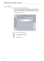
Страница 246: ...CCI TECU Operation 19 4 3 3 1 Overview This tab shows the settings for speed the power take off and the 3 point hitch ...
Страница 272: ...CCI Command GPS track guiding and section control Operating instructions Reference CCI Command v4 ...
Страница 362: ...91 Mark line Change the position of the marker Move reference track to the left Move reference track to the right ...
Страница 366: ...CCI GPS GPS settings and tractor geometry Operating instructions Reference CCI GPS v2 ...
Страница 388: ...CCI Courier Task data exchange between farm PC and terminal Operating instructions Reference CCI Courier v2 0 ...
Страница 389: ...2 Copyright 2014 Copyright by Competence Center ISOBUS e V Albert Einstein Str 1 D 49076 Osnabrück Version number v2 01 ...


