background image


Page 13 of 40 


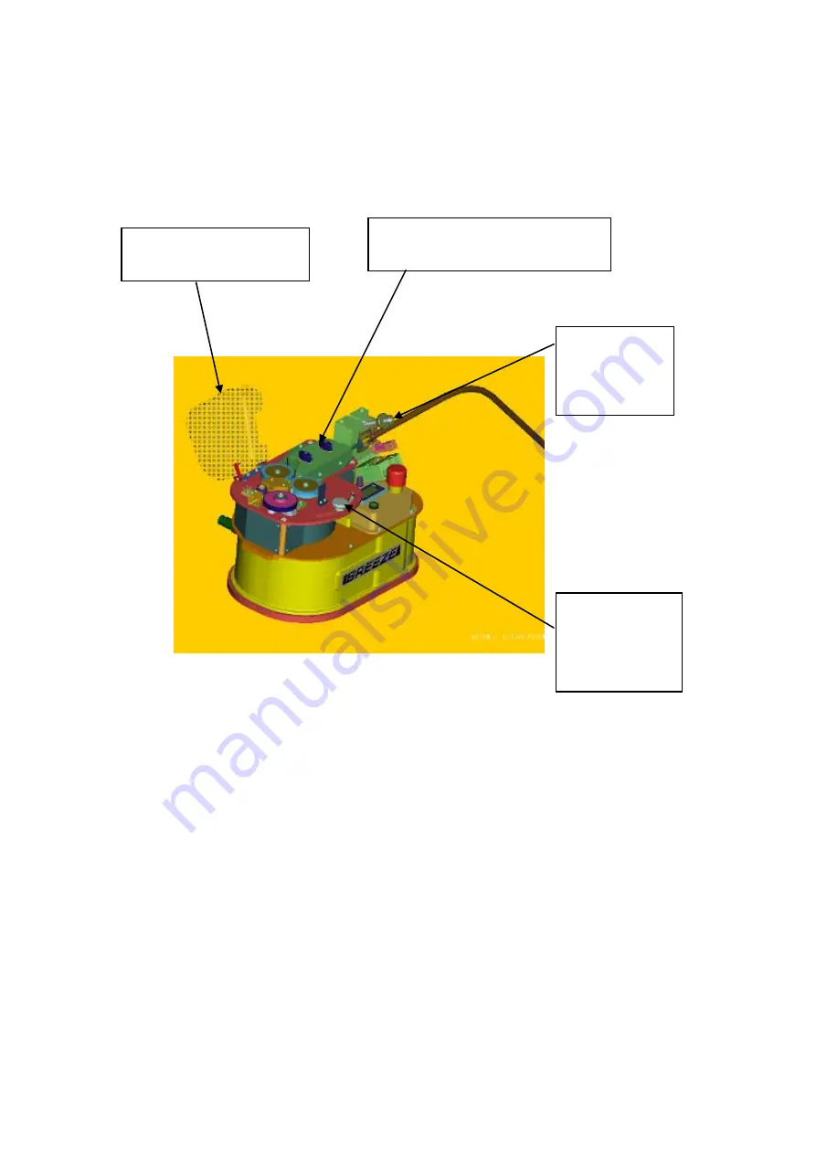
Fit the cable through the machine. 


Hold back the measuring wheel, so that the pressure spring is compressed.   


Raise the clear cover to 
expose the roller drive. 

Move the close 
assembly.  to 
the far right to 
fully open the


rollers 
 

Loosen the thumb nuts and 
retract the cable guide top


plate. 

Loosen the 
thumb nut and 
open the seal 
housing  

Содержание BREEZE

Страница 1: ...bsite www cbsproducts com OPERATING MANUAL C 1300 04 T BREEZE Serial Numbers 0161 Onwards See revision 03 for earlier models CABLE BLOWING MACHINE Copyright 2004 by CBS Products Limited All rights reserved No part of this publication may be copied reproduced or transmitted in any form whatsoever without the written permission of CBS Products Ltd ...

Страница 2: ...thor 01 03 08 06 Original issue A Sibun 02 05 03 08 Programming Instructions Updated A Sibun 03 03 10 08 Operating Procedure and pictures updated A Sibun 04 13 10 08 Programming Instructions Updated A Sibun 05 30 01 12 Responsible Person Updated L Kilpin ...

Страница 3: ...rocedure for re positioning the measuring system fixed roller 11 0 Procedure for replacing the air box housing seal 12 0 Procedure for changing the air box infeed guide 13 0 Procedure for changing the drive rollers 14 0 Monthly Service check list 15 0 Service History Record 16 0 Tube integrity and Lubrication 17 0 Recommended Spares List APPENDICES Appendix 1 Cable and tube insert selection chart ...

Страница 4: ... machine and isolate compressed air and electrical services to carry out lubrication and servicing 6 Check machine before starting for worn or damaged parts Check for signs of loose nuts and bolts etc 7 If machine is left unattended ensure that unauthorised use is prevented 8 Never leave the machine unattended whilst in use 9 Consider the use of safety barriers especially when used in public place...

Страница 5: ... the cable Do not turn the air on until a reasonable length of cable 50m has been installed into the tube 24 Ensure the cable drum rotates freely on its stand the cable should leave from the top of the drum 25 The cable should enter the machine in a clean and dry condition In damp dusty atmospheres the cable should be cleaned continuously as it enters the machine FAILURE TO DO SO MAY RESULT IN PER...

Страница 6: ...far end of the cable run Severe personal injury may result Never open the air chamber when pressurised Only authorised fully trained personnel should operate the air compressor GENERAL ELECTRICAL SAFETY INSTRUCTIONS The machine has electronic and electrical power and control circuits Electric shock hazards exist that could result in severe personal injury Observe the following precautions to avoid...

Страница 7: ...NG FITTINGS ARE SUITABLE FOR OPERATING AT 15 BAR AIR PRESSURE TUBE CLAMP SECURELY TIGHTENED COMPRESSOR CAPACITY 15 BAR AND SUITABLE FOR SIZE OF TUBE BEING USED CABLE DRUM MUST BE LOCATED DIRECTLY BEHIND AND IN LINE WITH THE BLOWING MACHINE AIR CHAMBER DRIVE ROLLERS CABLE GUIDES MUST BE CLEAN AND FREE FROM DEBRIS SLUDGE DIRT WATER AND LUBRICANT THE CABLE MUST BE HAND GUIDED INTO THE BLOWING MACHINE...

Страница 8: ...nsure that the cable is protected during installation Due to the variety and different methods of cable manufacture the responsibility of checking the cable compatibility with the equipment lies with the operator Therefore CBS products cannot accept liability for any damage to the cable ...

Страница 9: ...During installation the torque applied to the cable by the rollers can be adjusted to prevent the cable buckling and to prevent damage to the cable A full range of accessories is available to allow the machine to handle a wide range of cables and tubes This machine has the added function of high low torque selection this has been developed to give greater sensitivity when operating in the low torq...

Страница 10: ...ble speed 0 50m min 0 164 ft min Maximum pushing force 16 Kg 35 lb Maximum air pressure 15 bar 210 psi Power requirements 115 or 230V ac 50 60 Hz Factory Set Gripping force rollers onto cable 1 40 Kg 1 88 lb Weight 23Kg approx 50 lbs approx Dimensions ht x length x width 250mmx390mmx270mm 10 x15 3 8 x10 5 8 ...

Страница 11: ...elow this shows a plan view of the recommended set up Ensure the machine is secure either on its own stand or a separate suitable stand Ensure the machine is fitted with the appropriate guides and collets to suit the cable being installed and tubes into which the cable is to be installed See Appendix 1 for details of interchangeable parts To set the machine up to install cable it will be necessary...

Страница 12: ...connector Slide a suitable size O ring over the end of the tube Fit the tube into the end of the air box housing so that it protrudes approx half way into the housing as shown in the sketch position the O ring so that it sits against the seal face as shown in the sketch Once the tube has been positioned the tube clamp may be closed the swing bolt swung down and the thumb nut tightened the tube is ...

Страница 13: ...g wheel so that the pressure spring is compressed Raise the clear cover to expose the roller drive Move the close assembly to the far right to fully open the rollers Loosen the thumb nuts and retract the cable guide top plate Loosen the thumb nut and open the seal housing ...

Страница 14: ...cover over the feed rollers Close the drive roller assembly onto the cable as follows The sketch shows the drive roller close thumbscrew slightly loosened The assembly is free to move This thumbscrew is fixed to the clamp arm lever The clamp arm lever controls the position of the roller assembly As the clamp arm is moved around the quadrant the rollers move together and apart When the clamp arm is...

Страница 15: ...ng The air inlet to the machine must terminate in a suitable connector Connect the electrical supply to the machine The electrical supply must terminate in an RS type 3 way cable connector fitted with sockets Adaptors are available to suit any required existing connector speak to our sales department for full details and specification of connector If the power supply lead supplied with the Breeze ...

Страница 16: ...Page 16 of 40 The machine is now ready to start the cable installation ...

Страница 17: ... installation The CBS Breeze machine is ideally suited to this type of operation it may be coupled with a second machine to increase the distance a single cable can be installed without joins The only difference between this set up and the set up for installing cable with the machine above ground is that there will be no drum stand carrying the cable drum The cable will be exiting from one side of...

Страница 18: ...s Turn counter clockwise to reduce the amount of torque pushing force applied to the cable by the rollers Speed control This potentiometer controls the motor speed turn this clockwise to increase the speed of the rollers and the cable Turn counter clockwise to reduce the speed Emergency stop Pushing this red knob downwards will stop the rollers feeding the cable This knob may be used to switch the...

Страница 19: ...nnector see Connect the electrical supply to the machine Page 15 of this manual Select the high low torque switch position in general low torque should be used for cable diameters less than 2 5mm or 0 01 If in doubt initially use the low torque setting It is also recommended for small cables with low friction coatings that softer black drive wheels are used to improve blowing performance DO NOT SW...

Страница 20: ...the cable being damaged by buckling 6 0 Maintenance The CBS Cable Blowing Machine has been designed to give reliable trouble free service over long periods The machine requires no sophisticated maintenance procedures simple common sense checks and precautions are all that are needed The main source of breakdown and or malfunction of a machine being used outdoors is contamination by the elements th...

Страница 21: ...used this is a solvent the safety precautions outlined on the COSHH document supplied with the chemical must be observed Measuring roller this should be kept clean Build up of dirt etc on the faces will cause faulty readings of speed and or distance Clean with warm soapy water wash off and allow to dry For stubborn marks and build up M E K methyl ethyl ketone may be used this is a solvent the safe...

Страница 22: ...housing O rings Rebuild the machine to current build standard Test As a general rule every time an interchangeable part is removed and replaced by a part of a different size shape etc the part being removed should be thoroughly cleaned before being returned to its box Similarly the cavity from which it was removed can also be cleaned prior to the assembly of the replacement part Airbox parts keep ...

Страница 23: ... bolt to open the tube clamp housing Remove the insert To fit the new inserts reverse the disassembly procedure Repeat the process for the insert in the other housing half Loosen the thumb nut rotate the swing bolt to open the air box Loosen and remove the m4 fixing screw Do not lose this screw it will be needed for the replacement insert Remove the insert Repeat the process for the insert in the ...

Страница 24: ...ing wheel does not deflect the cable Loosen and remove the 2 m3 screws securing the upper housing onto the lower housing Loosen and remove the m2 5 screw securing the insert into the upper housing Remove the insert Repeat the procedure for the insert in the lower housing To fit the new inserts reverse the disassembly procedure Loosen the m4 screw holding the roller support bracket in position Posi...

Страница 25: ...ove Place the pre cut length in the groove with some of the excess length overhanging each end of the groove Trim the seal level with the end of the groove each end Take care not to damage the seating diameter for the cable seal and the tube seal Take care to make the cut accurately in line with the end of the groove the cable seal and tube seal need to make an effective seal against the ends of t...

Страница 26: ...ics This will allow the cable to be pushed with high torque whilst being compressed lightly If this type of roller is needed the CBS Products Ltd sales office will be able to advise on part numbers etc To fit this roller it will be necessary to remove the standard roller the procedure is as follows Remove the airbox infeed guide Loosen and remove the 2 m3 fixing screws Do not mislay these screws t...

Страница 27: ...f what service has been carried out and when 1 Check the tool box ensure all tools and interchangeable parts are present clean and ready for use 2 Clean the outside of the machine take care not to damage the rollers or springs 3 Check the measuring wheel ensure it runs freely and that the speed distance functions respond when the wheel is rotated 4 Check the measuring wheel fixed roller make sure ...

Страница 28: ...Page 28 of 40 15 0 SERVICE HISTORY RECORD Service no Date Carried out by Record of service repair ...

Страница 29: ... in place of the cable The tube can then be pressurised without running the roller drive CAUTION ANY OBJECT INADVERTENTLY LEFT IN THE TUBE DURING THE TUBE LAYING MAY BE EXPELLED FROM THE END OF THE TUBE WITH HIGH FORCE AND VELOCITY IT IS IMPERATIVE THAT NO PERSONNEL BE IN THE VICINITY OF THE END OF THE TUBE OR THAT A SUITABLE DEVICE IS FITTED TO THE END OF TH E TUBE TO ARREST ANY EXPELLED OBJECT T...

Страница 30: ... the tube Once the tube integrity has been confirmed by the method outlined above The tube may be lubricated Open the air box and tube clamp assembly as shown in the sketch above withdraw the tube and raise it so that the lubricant will pour into it easily and not overflow from the top Pour lubricant of recommended quality and quantity down the tube A recommended quantity is 100ml per 1km of tube ...

Страница 31: ... Cable end tips 5 Lubricant 6 2 mm cord seal 7 5 AMP 315 mAMP fuses For spare parts always quote the machine type and serial number and contact CBS Products Ltd Pillings Road OAKHAM Rutland LE15 6QF TEL 01572 723665 FAX 01572 756009 E MAIL sales cbsproducts com Website www cbsproducts com ...

Страница 32: ...LY 2 5 TO 3 0 mm DIAMETER C 1300 CBL 3038 CABLE SEAL COLLET ASSEMBLY 3 0 TO 3 8 mm DIAMETER C 1300 CBL 3850 CABLE SEAL COLLET ASSEMBLY 3 8 TO 5 0 mm DIAMETER C 1300 CBL 5064 CABLE SEAL COLLET ASSEMBLY 5 0 TO 6 4 mm DIAMETER C 1300 CBL 6480 CABLE SEAL COLLET ASSEMBLY 6 4 TO 8 0 mm DIAMETER CABLE SEAL C 1300 CS 1 4 CABLE SEAL 1 4 mm C 1300 CS 1 6 CABLE SEAL 1 6 mm C 1300 CS 2530 5 CABLE SEAL 2 5 TO ...

Страница 33: ...he maximum counter clockwise position In this position both torque and speed will be minimum Zero The sketch to the right shows the torque and speed control potentiometers set in the maximum clockwise position In this position both torque and speed will be maximum see specification for details The torque control setting will allow the cable to be installed efficiently and without damage It is of v...

Страница 34: ...ith high stiffness may be less stiff than a large cable with medium stiffness The table reflects this If there is any doubt in the first instance err on the low side i e select a lower U figure Cable dia mm Cable stiffness Stiffness coefficient U 2 0 3 5 Low U1 Medium U1 High U2 3 5 5 0 Low U1 Medium U2 High U3 5 0 6 5 Low U2 Medium U3 High U5 6 5 8 0 Low U2 Medium U4 High U6 2 Assess the coeffici...

Страница 35: ...ontrol potentiometer approximately one half of the way around its maximum travel etc There is an alternative way of arriving at the appropriate setting for the torque control potentiometer Do the following Select a sample of the cable to be used Pass the cable through the machine as described in the manual Feed the cable into the beginning of a length of sample tube say 5 metres long Seal the open...

Страница 36: ...he cable Eventually the rollers will stop turning because the torque limit has been reached It is worth noting at this stage that this approach may result in a great deal of force being applied to the cable More than the cable can withstand without sustaining damage sometimes it may be that the cable may be protected from buckling by a combination of torque control setting and slip The main purpos...

Страница 37: ...de 111 by pressing RST to change numbers and SEL to skip to the next number Once correct Press and Hold SEL for 2 seconds Pro no should now be flashing press RST Press RST to move through the various sections 1 input 2 rate 3 dsplay sections 4 and 5 will be unavailable see the next page of instructions for the parameters required Press SEL to enter that section To change the value of a parameter p...

Страница 38: ...d SEL CNT A RST TO ZERO if correct press SEL CNT A DIR NOR if correct press SEL CNT A LD 0 once correct press Hold SEL CNT B BAT NO if correct press SEL RST P UP NO if correct press SEL USER INP NO if correct press SEL Press RST Twice Rate Parameters 2 RATE RATE ENB YES if correct press SEL RATE DP 0 if correct press SEL RATE DSP 60 once correct press Hold SEL RATE INP 97 9 Metric m min or 29 8 Im...

Страница 39: ...Page 39 of 40 ...

Страница 40: ...0 04 T SERIAL NUMBER 0254 DESCRIPTION MICRO CABLE BLOWING MACHINE MANUFACTURED IN ACCORDANCE WITH THE SUPPLY OF MACHINERY SAFETY REGULATIONS 1992 S I 1992 3037 AND IN CONFORMANCE WITH THE ESSENTIAL HEALTH AND SAFETY REQUIREMENTS RESPONSIBLE PERSON MR ANDREW SIBUN TECHNICAL MANAGER SIGNED ON BEHALF OF RESPONSIBLE PERSON MR TONY LEWIS OPERATIONS DIRECTOR ...

Отзывы: