USER & PARTS MANUAL
CS940
21
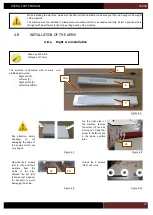
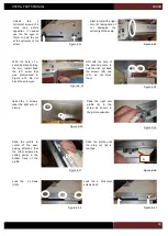
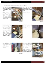
Lock the 3 screws
(ULF) from the top of
the profile.
Figure 4-36
Still holding the arm,
install the nut so they
are inside the the
track of the profile.
Figure 4-37
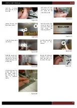
Holding the arm, lock
the screws under it.
Figure 4-38
With the bubble level,
check the level of the
arm while locking the
front
screw
(see
following pictures).
Figure 4-39
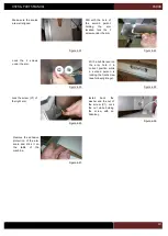
Lock the screws under
the left arm.
Figure 4-40
Figure 4-41
Lock the screw (V6) in
the
front
of
the
machine.
Install the washer and
nut on the screw (V6)
and lock the nut while
holding the screw with
an Allen key.
Figure 4-42
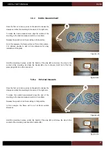
Remove the adhesive
protection under the
scale and stick it on
the table of the saw.
Figure 4-43
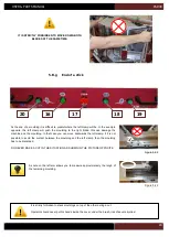
A hole will receive the
locking Allen key of
the blade, install in
this hole the key to
have
it
available
easlily.
Figure 4-44
Содержание CS 940
Страница 1: ...USER PARTS MANUAL Version 5 05 2017 Z27456 Version 1 07 2014 ...
Страница 12: ...USER PARTS MANUAL CS940 12 2 E CUTTING CAPACITY ...
Страница 13: ...USER PARTS MANUAL CS940 13 2 F NEEDED SPACE ...
Страница 37: ...USER PARTS MANUAL CS940 37 ...
Страница 46: ...USER PARTS MANUAL CS940 46 2 E CAPACITE DE COUPE ...
Страница 47: ...USER PARTS MANUAL CS940 47 2 F PLAN D ENCOMBREMENT ...
Страница 71: ...USER PARTS MANUAL CS940 103 V CERTIFICATE CERTIFICAT DE CONFORMITE ...
Страница 72: ...USER PARTS MANUAL CS940 104 ...

