USER & PARTS MANUAL
CS940
19
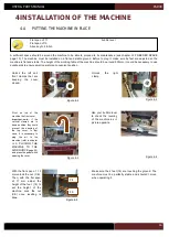
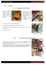
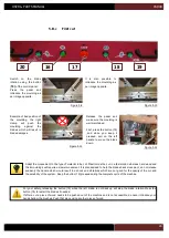
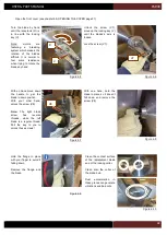
Make sure the scales
are well aligned.
Figure 4-22
Figure 4-21
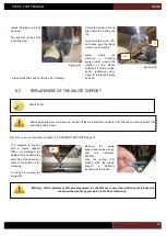
Still with the help of
the
second
person
holding
the
arm
levelled, lock the 3
screws under the arm.
Lock the 2 screws
under the arm.
Figure 4-23
With a bubble level on
the arm, hold it in
correct position while
a second person is
locking the front screw
(see following image).
Figure 4-24
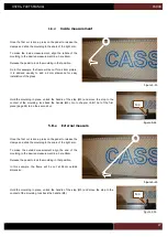
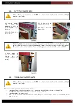
Lock the screw (V1) of
the right arm.
Figure 4-25
Install
back
the
washer and the nut of
the screw (V1). Lock
the nut while holding
the screw with an
Allen key.
Figure 4-26
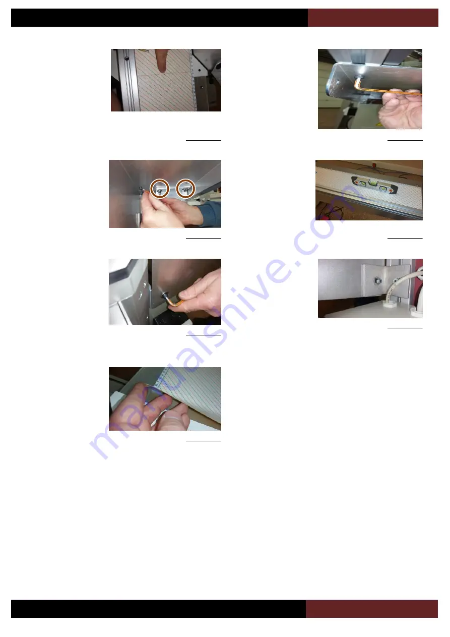
Remove the adhesive
protection of the arm
scale and stick it on
the
table
of
the
machine.
Figure 4-27
Содержание CS 940
Страница 1: ...USER PARTS MANUAL Version 5 05 2017 Z27456 Version 1 07 2014 ...
Страница 12: ...USER PARTS MANUAL CS940 12 2 E CUTTING CAPACITY ...
Страница 13: ...USER PARTS MANUAL CS940 13 2 F NEEDED SPACE ...
Страница 37: ...USER PARTS MANUAL CS940 37 ...
Страница 46: ...USER PARTS MANUAL CS940 46 2 E CAPACITE DE COUPE ...
Страница 47: ...USER PARTS MANUAL CS940 47 2 F PLAN D ENCOMBREMENT ...
Страница 71: ...USER PARTS MANUAL CS940 103 V CERTIFICATE CERTIFICAT DE CONFORMITE ...
Страница 72: ...USER PARTS MANUAL CS940 104 ...

